Robust Camera-to-Mocap Calibration and Verification
for Large-Scale Multi-Camera Data Capture
Abstract
Optical motion capture (mocap) systems are widely used for ground-truth capture in AR/VR, SLAM and robotics datasets. These datasets require extrinsic calibration to align mocap coordinates to external camera frames—a step that is subject to multiple sources of error in practice, and failures often go undetected until they corrupt downstream data. These issues are compounded for fisheye cameras, where spatially non-uniform distortion makes both calibration and verification more challenging. We present a calibration and verification system designed for this setting. Concretely, we target robustness to board-to-marker attachment variation, optimization initialization ambiguity, and session-to-session calibration drift after deployment. The calibration jointly estimates camera extrinsics and the board-to-marker transform, and uses a staged solver to improve convergence reliability under ambiguous initialization. The verification component, Lollypop, provides fast, operator-independent assessment through a measurement chain entirely independent of the calibration data. In experiments on a Meta Quest 3 headset with fisheye cameras, our calibration matches or outperforms Sturm et al. [23], and Lollypop reliably detects calibration degradation over time. The system has been deployed and verified in production data collection pipelines.


1 Introduction
Optical motion capture (mocap) is a standard source of ground-truth pose data for hand tracking [30, 15, 5], visual-inertial SLAM [20, 2], and AR/VR datasets. To use this ground truth in camera images, one must estimate an extrinsic calibration that maps the mocap coordinate frame to each camera frame. This calibration step is often under-documented in prior work [30, 15, 5, 20, 2]: calibration quality is typically assumed rather than explicitly validated. In practice, calibration is vulnerable to several sources of error. Capture systems are operated by humans, hardware is handled between sessions, and the physical geometry can change without being reflected in standard quality metrics. These errors can silently propagate into corrupted ground truth, degraded models, and irreproducible results.
The calibration itself is a hand-eye problem [26]: given a camera and a mocap system that both observe a moving calibration board with attached retroreflective markers, estimate the rigid transform from the mocap world frame to each camera frame. A central challenge is the board-to-marker transform, i.e., the rigid offset between the calibration pattern coordinate frame and the attached mocap rigid body. Standard approaches assume this transform is precisely known [23]. In practice, this is a fragile assumption: retroreflective markers are reattached, shifted, or replaced between sessions, and the physical relationship between markers and the calibration pattern can drift over time without detection. For fisheye cameras, common in AR/VR headsets and SLAM systems, strong spatially non-uniform distortion further complicates both calibration and verification. Figure 2 shows examples where inaccurate calibration produces visibly misaligned reprojected mocap markers and hand-tracking ground truth.
Verification is equally problematic. The standard quality metric—board reprojection error—is the residual of the calibration optimization itself, computed on the same data used to estimate the parameters. It is inherently self-referential: a calibration can report low board RMS while harboring significant errors in regions not probed by the calibration data. The alternative is visual inspection (Fig. 2), where an operator examines reprojected markers and subjectively judges alignment. This is subjective, inconsistent across operators, and does not scale.
We present a robust calibration and verification system designed for large-scale data collection. In this paper, robustness has three concrete meanings: (i) robustness to board-to-marker attachment variation across sessions, (ii) robustness of optimization to ambiguous or poor initialization, and (iii) robustness of calibration quality control to deployment-time drift. The calibration jointly estimates camera extrinsics and the board-to-marker transform, and uses a staged optimization pipeline to improve convergence reliability under ambiguous initialization. The verification component, Lollypop, uses a separate recording with a fiducial-marker/mocap rigid body to test the calibration through a measurement chain entirely independent of the calibration data, providing a fast, objective, operator-independent pass/fail decision. The system has been deployed in production capture pipelines.
Our contributions are:
-
1.
A joint calibration that removes the known-board-to-marker assumption, making calibration robust to marker placement variation across sessions. Benchmarked against Sturm et al. [23].
-
2.
A staged solver (random-restart Procrustes, 3D refinement, and 2D reprojection refinement) that improves convergence reliability under difficult initialization.
-
3.
Lollypop, a verification device and metric providing fast, operator-independent calibration assessment through an independent measurement chain.

2 Related Work
Camera calibration and fisheye models.
The foundational work for camera calibration using planar targets was established by Zhang [28], building on earlier work by Tsai [27] that first characterized radial distortion. For fisheye and wide-angle lenses, specialized distortion models have been developed. A widely adopted approach is the generic polynomial model of Kannala and Brandt [11], which forms the basis of the Fisheye62 model used in this work. Other popular methods, such as the OCamCalib toolbox by Scaramuzza et al. [18], model the projection function as a Taylor series expansion, providing a flexible framework for a wide range of omnidirectional cameras. More recently, Tezaur et al. [24] proposed a non-central model that extends Scaramuzza’s work to account for angle-dependent viewpoint shifts, addressing a key limitation of central models where the single viewpoint assumption can be violated in fisheye cameras, especially when observing objects at close range.
Camera-to-mocap calibration.
Calibrating a camera to an external tracking system is a form of hand-eye calibration. Tsai and Lenz [26] formulated the single-unknown case as ; Zhuang et al. [29] extended this to the two-unknown form , jointly solving for the robot-world and tool-flange transforms. Dornaika and Horaud [4] proposed a nonlinear optimization formulation for the same problem. In the camera-mocap setting, corresponds to the board-to-marker transform and to the camera extrinsic. Sturm et al. [23] simplify the problem by assuming is precisely known, reducing to a single unknown per camera. Chiodini et al. [3] address the camera-to-mocap problem directly by using the mocap system’s own retroreflective spherical markers as the calibration target, solving for the camera-to-mocap transform via P3P-RANSAC followed by nonlinear reprojection-error minimization, and providing a Monte Carlo uncertainty analysis of the result. However, like Sturm et al., they provide no independent means of verifying calibration quality after the fact.
The known-board-to-marker assumption is practical when markers can be precisely placed, but becomes fragile in production environments where markers are reattached between sessions, boards are rebuilt, or the board-to-marker relationship drifts over time. Our approach treats as a free variable and solves for it jointly with , removing this assumption.

Datasets using camera-mocap calibration.
Camera-to-mocap calibration underpins ground-truth generation across several application areas. The TUM RGB-D benchmark [23] used a MotionAnalysis system to provide ground-truth poses for an RGB-D sensor; the authors reported extrinsic calibration errors of 3.25–4.03 mm, but did not discuss the calibration algorithm in detail. In visual-inertial SLAM, TUM-VI [20] and EuRoC [2] use mocap-derived trajectories as ground truth, with the camera-to-mocap extrinsic determining how trajectory accuracy translates to image-space evaluation.
For human understanding, Human3.6M [10] calibrated four video cameras against a Vicon system, reporting a mean reprojection error of 0.17 px but their process involved error-prone manual labeling of markers in image frames. Assembly101 [21] tracks egocentric head pose via a mocap rigid body on a headset; the paper claims “sub-pixel accuracies” for the camera rig calibration but provides no specific numerical metrics or repeatability analysis. Hand-object interaction datasets including ARCTIC [5] use dense Vicon systems (54 cameras) and calibrate using the reflective markers themselves as targets. Across all these works, calibration procedures are described briefly and sometimes rely on manual, error-prone procedures; independent verification of calibration quality—particularly across sessions or in the presence of real-world perturbations—is also not addressed.
Calibration quality verification.
The most common quality metric is reprojection error on the calibration data itself [28]—the residual of the optimization and therefore inherently self-referential. This limitation extends to camera-to-mocap calibration; for example, Schofield et al. [19] estimate camera-mocap extrinsics using retroreflective markers but verify the result solely via the reprojection error of those same markers. Hold-out validation provides partial independence but uses the same target and detection pipeline. Richardson et al. [16] present AprilCal to improve repeatability, but do not address independent post-calibration verification against an external reference. Multi-view consistency checks [6] verify internal consistency but cannot detect systematic errors shared across views. As Shu et al. [22] note, evaluating hand-eye (camera-to-mocap) calibration in real-world systems is inherently difficult because the true physical offset is rarely available, forcing reliance on indirect proxy metrics like trajectory alignment. These approaches share a common limitation: they evaluate calibration quality using the same measurement chain—target, detector, data distribution—employed during estimation. Few provide a verification protocol that is fully independent of the calibration procedure.
Our work addresses both axes: a joint estimation formulation robust to board-to-marker uncertainty, paired with an independent verification device and protocol that uses a separate recording and detection pipeline to test the calibration result.
3 Calibration Method
We address the camera-to-mocap calibration problem: given a camera rigidly mounted on a mocap-tracked platform and a calibration board that is simultaneously visible to the camera and tracked by the mocap system, estimate the rigid transform from the platform’s mocap frame to the camera frame. This is an instance of the hand-eye calibration problem [29]. Unlike prior work [23] that assumes the board-to-marker transform is precisely known, our formulation treats it as a free variable estimated jointly with the camera extrinsics.
3.1 Problem Formulation
Given a camera and a mocap system both observing a planar calibration board with attached retroreflective markers (Fig. 4), the board is simultaneously detected in the camera’s images and tracked in 3D by the mocap system.

A 3D point on the calibration target is projected into camera at frame via the following chain:
| (1) |
where:
-
•
is the -th corner coordinate in the target’s local frame,
-
•
is the rigid transform (3 rotation + 3 translation DOFs) from the target frame to the mocap rigid body frame, shared across all cameras and frames,
-
•
is the mocap-reported rigid body pose at frame (known),
-
•
is the camera extrinsic, mapping mocap world coordinates into the camera frame,
-
•
is the camera projection function to produce pixel coordinates using intrinsic parameters .
Our goal is to estimate the unknown transforms and for all cameras , and optionally to refine the intrinsic parameters . In many settings, initial intrinsic estimates are already available from factory or online calibration (as on the Meta Quest 3) or from a separate intrinsic calibration step, and can be held fixed or used as a strong initialization.
3.2 Optimization Objective
Classical approaches first estimate per-frame board poses via PnP, then solve from pairwise relative motions, discarding the original pixel observations. While our initialization also uses PnP to bootstrap the rigid transforms (Sec. 3.3), the final objective is direct 2D reprojection error against the raw marker detections, cast as a bundle adjustment [25, 13]. The residual for marker at frame observed by camera is:
| (2) |
where is the detected 2D corner. The full objective is:
| (3) |
The regularization term penalizes deviation of intrinsic parameters from priors : the principal point is regularized toward the image center, distortion coefficients toward zero, and focal length is left effectively unregularized. This prevents degenerate solutions when detections are sparse.
3.3 Initialization and Solution
Direct minimization of the 2D objective (Eq. 3) is susceptible to local minima. We address this with a three-stage pipeline in which the first two stages operate on an auxiliary 3D point-matching objective that remains well-defined even for grossly incorrect estimates, and only the final stage optimizes the full 2D reprojection error.
3D point-matching objective.
For each frame and camera , we run PnP [12] on the 2D detections using the known marker geometry and initial intrinsic estimates to recover a per-frame board pose in camera space. This yields reference 3D positions for each detected marker , computed once and held fixed throughout initialization. The 3D error measures how well the kinematic chain reproduces these references:
| (4) |
Unlike the 2D reprojection error, which requires points to lie in front of the camera and project within the image, is well-defined for any configuration of the rigid transforms—even when the camera is pointed away from the board. This makes it suitable for coarse initialization where the current estimate may be far from the solution. The PnP-derived references do not participate in the final 2D objective; they serve only to guide the first two stages toward the correct basin of convergence. Intrinsic parameters are held fixed during both stages.
Stage 1: Random-restart Procrustes.
The board-to-marker transform is the most critical variable to initialize correctly. Because the orientation of the mocap rigid body frame relative to the printed pattern is unknown a priori, may be initialized with an arbitrarily wrong rotation. If, for example, is off by 180°, each camera independently concludes that the markers it observes lie on the reverse side of the board and places itself on the wrong side of the room—a deep local minimum from which gradient-based solvers cannot escape.
To resolve this ambiguity, we sample 30 well-distributed candidate rotations for via a greedy farthest-point algorithm on uniform random rotations, using Frobenius distance . For each candidate, we initialize the rotation of and run iterative Procrustes alignment: each transform in the chain is solved in turn via closed-form SVD-based rigid registration [1] on the 3D correspondences from Eq. 4, with the board-to-marker transform solved last to prevent it from absorbing global rigid body motion. We select the candidate with the lowest . This stage requires no iterative matrix inversion and reliably identifies the correct rotation basin.
Stage 2: 3D error minimization.
Stage 1 solves each transform independently in closed form, which is fast but does not account for interactions between transforms. Using the best Procrustes initialization, a Gauss-Newton solver with Levenberg-Marquardt damping [14] minimizes (Eq. 4), jointly refining all rigid transforms simultaneously. This yields a geometrically accurate estimate suitable for initializing the 2D reprojection stage.
Stage 3: 2D reprojection refinement.
Using the Stage 2 result as initialization, the same solver minimizes the full 2D objective (Eq. 3), jointly optimizing rigid transforms and camera intrinsics against pixel-level detections. Iteration terminates when improvement drops below with .
The three-stage approach ensures global convergence (Stage 1), geometric accuracy (Stage 2), and pixel-level precision (Stage 3). Rotations are parameterized via the exponential map [8] with 6-DOF (3 rotation + 3 translation) incremental updates; all Jacobians are computed analytically.
4 Verification Method

We present Lollypop, a device and method for independently verifying camera-to-mocap calibration. The key idea is to compare two independent estimates of a device’s image position—one from fiducial detection, one from mocap projection through the calibration—using a separate recording collected after calibration is complete.
4.1 Physical Device
The Lollypop device consists of two rigidly coupled components: an ArUco [7, 17] fiducial marker board and a mocap rigid body comprising six retroreflective markers. The board is printed on adhesive-backed polypropylene and mounted to a rigid backing panel. The mocap markers are 8 mm circular sections of 3M Scotchlite 7610 retroreflective tape applied directly to the board surface. The ArUco board provides the image-space reference, while the mocap rigid body provides the 3D tracking-space reference.
The rigid body uses six mocap markers rather than the minimum three for two reasons. First, the centroid of markers has tracking noise reduced by a factor of relative to a single marker, improving 3D position precision.
Critically, the device is constructed so that the ArUco board center and the mocap rigid body centroid are coincident by design, i.e., the 3D offset is 0. This is a fixed mechanical constraint of the rigid device. Unlike the calibration board’s board-to-marker attachment—which can shift between sessions and is estimated as part of the calibration solve (Sec. 3)—the Lollypop’s geometric relationship does not drift and is not re-estimated. This means projecting the mocap rigid body centroid through the calibration produces exactly the predicted image position of the ArUco board center.
4.2 Device Precision
The coincidence of the ArUco board center and mocap rigid body centroid is verified by direct measurement against the CAD design. The primary source of manufacturing error is the thickness of the retroreflective tape (0.12 mm), which raises the mocap marker centroids above the printed board plane. This height difference contributes zero error when the board is viewed at normal incidence (zenith) and a maximum of 0.12 mm at 90° grazing angle. In practice, ArUco detection is inherently limited to moderate viewing angles, bounding this error well below 0.12 mm; additional filtering on the detection viewing angle can further reduce its impact for tighter tolerance requirements.
4.3 Error Metric
For each frame where both the ArUco marker and the mocap rigid body are detected, we compare two independent estimates of the device center in the image (Fig. 6) in both 2D and 3D.
ArUco center.
The board center is estimated from the four detected corners via a 2D homography. Each corner is undistorted to normalized image coordinates using the camera model. A homography from a canonical unit square to these normalized positions is estimated, and the canonical center is warped through and mapped back to distorted pixel coordinates to yield . This operates entirely in the image domain without 3D pose estimation.
Mocap center.
Because the board center and rigid body centroid are coincident (Sec. 4.1), the mocap centroid projects directly as the predicted board center:
| (5) |
where is the world-to-camera extrinsic, composed with the inverse platform pose for headset-mounted cameras.
2D error.
The primary metric is the pixel-space Euclidean distance:
| (6) |
Both points are in distorted pixel coordinates, so this tests the full calibration chain including the distortion model.
3D error.
We also back-project to 3D at the depth of the projected mocap centroid, yielding a world-space ArUco position :
| (7) |
This gives error in millimeters but is not fully independent in the depth direction. We report both; 2D error is our primary measure.
5 Experiments
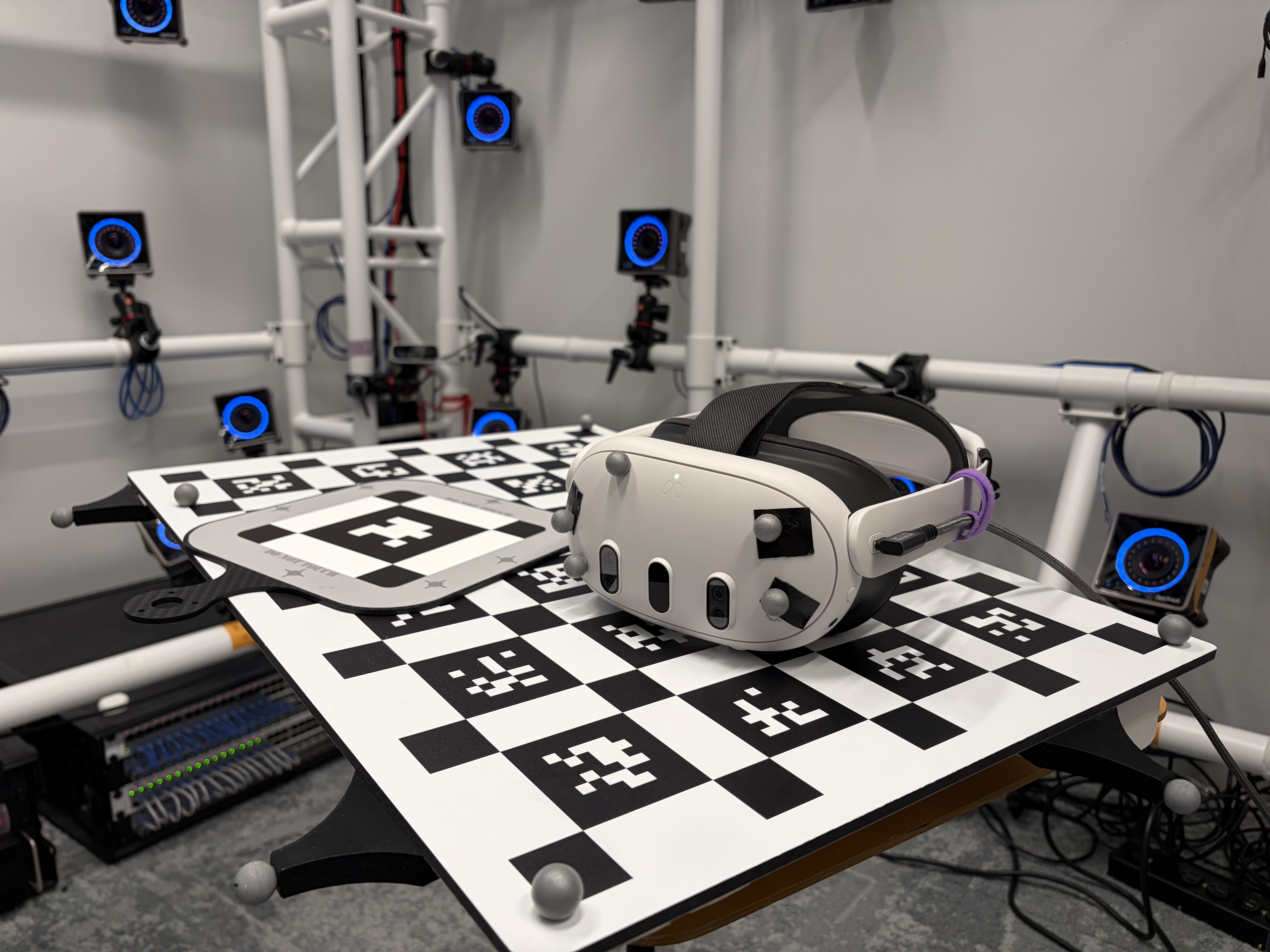
We evaluate on a Meta Quest 3 headset equipped with four fisheye cameras using the Fisheye62 distortion model, which extends Kannala-Brandt [11] with two tangential distortion coefficients (6 radial + 2 tangential parameters). Camera intrinsics are read directly from the device’s online calibration and held fixed; the solver optimizes only extrinsics and the board-to-marker transform. Headset camera images are hardware-synchronized with the mocap system, which provides rigid body poses of the calibration board and headset. A printed A2 fiducial board with 24 ArUco markers is used as the detection board. Each marker has a side length of 59 mm, with 29.5 mm spacing between neighboring markers. The layout also includes smaller black square patches at the grid intersections (and boundary intersections), which strengthens local contrast and helps stabilize corner localization. The four corners of each marker are used as known 3D reference points in the board coordinate frame during calibration. Our custom board follows the ChArUco principle of combining ArUco markers with checkerboard-style corner structure for robust corner localization [7, 17].
5.1 Calibration Benchmark
We compare our joint calibration (Sec. 3) against Sturm et al. [23] on five calibration board recordings. Both methods receive identical input: detected board corners and mocap rigid body poses of the board and headset. Sturm et al. requires the board-to-marker transform to be provided as a known input; our method estimates it jointly. We report both the self-referential board RMSE (reprojection error on calibration data) and the independent Lollypop 2D error from a separate verification recording.
Since no open-source implementation of Sturm et al. is available, we implement an approximation of their method. Using the calibration board shown in Fig. 4, we place four retroreflective markers at the corners of ArUco tags, forming a rigid body whose centroid-to-board-center offset is measured and held fixed as the known board-to-marker transform . Given this fixed , the reimplemented baseline solves for the camera extrinsic by minimizing reprojection error through the kinematic chain and the camera intrinsic model. The solver proceeds in two stages: an initial least-squares fit for basin capture, followed by robust refinement with Huber-weighted residuals [9]. In contrast, our method uses additional markers affixed to the outer perimeter of the board (Fig. 4) without requiring precise placement; the board-to-marker transform is treated as a free variable and estimated jointly with the camera extrinsics (Sec. 3), eliminating the need for error-prone manual measurement.
We collect five calibration recordings with the headset placed at different poses within the capture volume to vary the viewing geometry. For each recording, both methods are evaluated on the same set of detection results and mocap poses. We report the board reprojection RMSE, computed as the pooled per-point root-mean-square error over all detected corners:
| (8) |
where is the 2D reprojection residual (Eq. 2) and is the total number of detected corner observations across all frames.
| Board RMSE (px) | Lollypop RMSE (px) | |||
|---|---|---|---|---|
| Camera | Ours | Sturm | Ours | Sturm |
| Right Front | 0.12 | 1.04 | 0.22 | 1.87 |
| Left Front | 0.12 | 0.40 | 0.24 | 1.91 |
| Left Side | 0.08 | 0.81 | 0.44 | 1.76 |
| Right Side | 0.09 | 6.76 | 0.35 | 8.45 |
| Mean | 0.10 | 2.25 | 0.31 | 3.50 |
Tab. 1 shows that our method produces lower Lollypop error compared to the approximated Sturm et al. method across all five recordings.
5.2 Ablation Study
We ablate key components of the optimization pipeline to measure their individual contributions. Starting from the full method, we disable each feature in isolation and evaluate the resulting board reprojection RMSE on a representative calibration recording.
| Configuration | RMSE (px) | |
|---|---|---|
| Full pipeline (Stages 1+2+3) | 0.146 | — |
| w/o Stage 3 (2D reprojection) | 0.148 | +0.002 |
| w/o Procrustes initialization | 0.146 | +0.000 |
| Stage 1 only (no iterative refine.) | 43.000 | +42.900 |
Tab. 2 reveals that each stage serves a distinct role. Without any iterative refinement (Stage 1 only), error is worse (43 px), confirming that iterative optimization is essential. Procrustes initialization (Stage 1) does not improve final accuracy but resolves the rotation ambiguity in , reducing Stage 2 iterations from 11 to 6 ( convergence speedup). Its primary contribution is solver robustness: ensuring the Gauss-Newton solver lands in the correct basin, which is critical when the board-to-marker transform is far from identity or the board has near-symmetry. Stage 2 (3D error minimization) provides well-conditioned convergence from the coarse Procrustes initialization. Its smoother objective landscape, free of projection nonlinearity, reliably drives large initial errors down to the geometric minimum. Stage 3 (2D reprojection refinement) jointly refines intrinsics and achieves optimal pixel-level fit. On this recording the improvement over Stage 2 alone is marginal (0.146 vs. 0.148 px) because we fixed the intrinsics for controlled experiments; on recordings with poor factory calibration, Stage 3 is expected to contribute more substantially, reflecting the intrinsics adjustment that improves pixel fit while shifting 3D reconstruction.


5.3 Calibration Drift Over Time
A key motivation for independent verification is detecting calibration degradation that accumulates during normal use. Fig. 3 shows error measured over five successive verification recordings. Between recordings, the headset is repeatedly donned and doffed, and retroreflective markers are occasionally bumped or shifted to emulate real-world handling. Both pixel-domain and metric-domain RMSE increase over repeated use, demonstrating that a calibration performed initially can degrade overtime. Lollypop provides a per-session quick check that detects when recalibration is needed. Visualization of the mocap vs ArUco center on the raw image as shown in Fig. 6 also provides a way to spot check for any offset.
5.4 Spatially-Resolved Error Analysis
Aggregate metrics report a single number per camera, which is especially misleading for fisheye cameras where calibration quality varies across the image. Fig. 7 shows Lollypop error binned by image position for the same camera under accurate and inaccurate calibrations. The high-quality calibration exhibits uniformly low error across the image. The bad calibration shows lower error near the optical center and elevated error at the top/left periphery.
6 Conclusion
We have presented a complete calibrate-then-verify pipeline for camera-to-mocap systems with fisheye cameras. Our calibration method formulates the problem as a kinematic-chain bundle adjustment that jointly solves for camera extrinsics and the board-to-marker transform, eliminating the assumption that the latter is precisely known. Together with staged initialization and refinement, this improves robustness to attachment variation and initialization ambiguity. Benchmarked against Sturm et al. [23], our method produces substantially lower independent verification error across all cameras.
For verification, Lollypop provides an independent calibration check using a physical device that combines fiducial markers with mocap rigid bodies. In controlled experiments on fisheye cameras, Lollypop reliably offered observability into calibration degradation. Spatially-resolved error analysis reveals non-uniform calibration quality that aggregate metrics mask entirely: errors concentrate at the image periphery where lens distortion is strongest. Together with the repeated-use drift analysis, this supports robustness not only at calibration time, but also for deployment-time quality control.
The current approach requires optical mocap infrastructure for the 3D reference, and the 2D error metric primarily validates lateral calibration accuracy—depth-direction errors are less well constrained since the back-projection uses mocap-derived depth. A future extension using 3D fiducial arrangements (e.g., markers on multiple faces of a polyhedron) could address both limitations by improving viewing-angle coverage and enabling depth-direction verification.
In our production data collections, Lollypop cut validation time by over 50% and replaced subjective visual inspection with an objective pass/fail criterion. More broadly, we hope this paper helps shift calibration from an under-documented preprocessing step to a rigorously measured part of large-scale dataset construction, improving the quality and reproducibility of future datasets.
References
- [1] (1987) Least-squares fitting of two 3-D point sets. IEEE TPAMI (5), pp. 698–700. Cited by: §3.3.
- [2] (2016) The EuRoC micro aerial vehicle datasets. Int. J. Robotics Research 35 (10), pp. 1157–1163. Cited by: §1, §2.
- [3] (2018) Camera rig extrinsic calibration using a motion capture system. In IEEE Int. Workshop on Metrology for AeroSpace, pp. 590–595. Cited by: §2.
- [4] (1998) Simultaneous robot-world and hand-eye calibration. IEEE Trans. Robotics and Automation 14 (4), pp. 617–622. Cited by: §2.
- [5] (2023) ARCTIC: a dataset for dexterous bimanual hand-object manipulation. In CVPR, pp. 12943–12954. Cited by: §1, §2.
- [6] (2013) Unified temporal and spatial calibration for multi-sensor systems. In IEEE/RSJ IROS, pp. 1280–1286. Cited by: §2.
- [7] (2014) Automatic generation and detection of highly reliable fiducial markers under occlusion. Pattern Recognition 47 (6), pp. 2280–2292. Cited by: §4.1, §5.
- [8] (1998) Practical parameterization of rotations using the exponential map. J. Graphics Tools 3 (3), pp. 29–48. Cited by: §3.3.
- [9] (1964) Robust estimation of a location parameter. Annals of Mathematical Statistics 35 (1), pp. 73–101. Cited by: §5.1.
- [10] (2014) Human3.6M: large scale datasets and predictive methods for 3D human sensing in natural environments. IEEE TPAMI 36 (7), pp. 1325–1339. Cited by: §2.
- [11] (2006) A generic camera model and calibration method for conventional, wide-angle, and fish-eye lenses. IEEE TPAMI 28 (8), pp. 1335–1340. Cited by: §2, §5.
- [12] (2009) EPnP: an accurate O(n) solution to the PnP problem. IJCV 81 (2), pp. 155–166. Cited by: §3.3.
- [13] (2009) SBA: a software package for generic sparse bundle adjustment. ACM Trans. Mathematical Software 36 (1), pp. 1–30. Cited by: §3.2.
- [14] (1963) An algorithm for least-squares estimation of nonlinear parameters. J. Society for Industrial and Applied Mathematics 11 (2), pp. 431–441. Cited by: §3.3.
- [15] (2020) InterHand2.6M: a dataset and baseline for 3D interacting hand pose estimation from a single RGB image. In ECCV, pp. 548–564. Cited by: §1.
- [16] (2013) AprilCal: assisted and repeatable camera calibration. In IEEE/RSJ IROS, pp. 4618–4624. Cited by: §2.
- [17] (2018) Speeded up detection of squared fiducial markers. Image and Vision Computing 76, pp. 38–47. Cited by: §4.1, §5.
- [18] (2006) A toolbox for easily calibrating omnidirectional cameras. In IEEE/RSJ IROS, pp. 5695–5701. Cited by: §2.
- [19] (2018) Calibration for camera-motion capture extrinsics. In Int. Conf. Image and Vision Computing New Zealand (IVCNZ), pp. 1–6. Cited by: §2.
- [20] (2018) The TUM VI benchmark for evaluating visual-inertial odometry. In IEEE/RSJ IROS, pp. 1680–1687. Cited by: §1, §2.
- [21] (2022) Assembly101: a large-scale multi-view video dataset for understanding procedural activities. In CVPR, pp. 21064–21074. Cited by: §2.
- [22] (2024) A spatiotemporal hand-eye calibration for trajectory alignment in visual(-inertial) odometry evaluation. IEEE Robotics and Automation Letters 9 (6), pp. 5134–5141. Cited by: §2.
- [23] (2012) A benchmark for the evaluation of RGB-D SLAM systems. In IEEE/RSJ IROS, pp. 573–580. Cited by: item 1, §1, §2, §2, §3, §5.1, Table 1, Table 1, §6.
- [24] (2022) A new non-central model for fisheye calibration. In CVPR, pp. 5222–5231. Cited by: §2.
- [25] (1999) Bundle adjustment—a modern synthesis. In Int. Workshop on Vision Algorithms, pp. 298–372. Cited by: §3.2.
- [26] (1989) A new technique for fully autonomous and efficient 3D robotics hand/eye calibration. IEEE Trans. Robotics and Automation 5 (3), pp. 345–358. Cited by: §1, §2.
- [27] (1987) A versatile camera calibration technique for high-accuracy 3D machine vision metrology using off-the-shelf TV cameras and lenses. IEEE J. Robotics and Automation 3 (4), pp. 323–344. Cited by: §2.
- [28] (2000) A flexible new technique for camera calibration. IEEE TPAMI 22 (11), pp. 1330–1334. Cited by: §2, §2.
- [29] (1994) Simultaneous robot/world and tool/flange calibration by solving homogeneous transformation equations of the form . IEEE Trans. Robotics and Automation 10 (4), pp. 549–554. Cited by: §2, §3.
- [30] (2019) FreiHAND: a dataset for markerless capture of hand pose and shape from single RGB images. In ICCV, pp. 813–822. Cited by: §1.