Speak, Segment, Track, Navigate: An Interactive System for Video-Guided Skull-Base Surgery
Abstract
We introduce a speech-guided embodied agent framework for video-guided skull base surgery that dynamically executes perception and image-guidance tasks in response to surgeon queries. The proposed system integrates natural language interaction with real-time visual perception directly on live intraoperative video streams, thereby enabling surgeons to request computational assistance without disengaging from operative tasks. Unlike conventional image-guided navigation systems that rely on external optical trackers and additional hardware setup, the framework operates purely on intraoperative video. The system begins with interactive segmentation and labeling of the surgical instrument. The segmented instrument is then used as a spatial anchor that is autonomously tracked in the video stream to support downstream workflows, including anatomical segmentation, interactive registration of preoperative 3D models, monocular video-based estimation of the surgical tool pose, and support image guidance through real-time anatomical overlays. We evaluate the proposed system in video-guided skull base surgery scenarios and benchmark its tracking performance against a commercially available optical tracking system. Across three experimental trials, the vision-based method achieved a mean absolute tool-tip position error of mm and roll and pitch errors of and , respectively. The system completes tool segmentation and anatomy registration within approximately two minutes, substantially reducing setup complexity compared to conventional tracking workflows. These results demonstrate that speech-guided embodied agents can achieve competitive spatial accuracy while improving workflow integration and enabling rapid deployment of video-guided surgical systems.
I Introduction
Surgical interventions remain a cornerstone of modern patient care, yet their increasing technical complexity demands assistive technologies that integrate seamlessly into clinical workflows. This need is particularly crucial for complex procedures such as skull base surgery, where operable tissues and critical neurovascular structures are millimeters apart. [15] Due to this complexity, image guided assistance holds significant promise through integration of imaging, software, and computational intelligence to support intraoperative decision-making. [22] Given that skull base procedures are performed under continuous microscopic visualization, intraoperative video streams has emerged as a central sensing modality for real-time computer-aided assistance.
To enable such assistance, several surgical computer vision methods have been developed to extract actionable information from these video streams. Existing approaches address tasks such as instrument segmentation, anatomy segmentation, tool tracking, and video-based registration.[1] While these advances have enabled increasingly sophisticated perception capabilities, a fundamental limitation persists: existing algorithms are designed to perform a single predefined task. They operate independently and cannot be dynamically invoked according to the surgeon’s evolving intent. Consequently, coordinating heterogeneous tasks, such as instrument tracking, anatomical segmentation, preoperative model registration, and navigation, remains fragmented and workflow disruptive. It is not desirable that surgeons disengage from the operative field to interact with external navigation systems or manually configure computational tools.
Interactive segmentation frameworks based on vision foundation models (VFMs) partially address usability through prompt-driven paradigms. Models such as the SAM [7] enable category-agnostic segmentation via visual prompts, while Grounded SAM [19] extends this paradigm to text-conditioned segmentation. Although these approaches represent a shift toward more flexible human-machine interaction, they typically require direct visual inputs (e.g., clicks, strokes, or bounding boxes) or static textual prompts. They are not inherently designed for continuous, hands-free operation within dynamic surgical environments, nor do they orchestrate multiple downstream tasks beyond segmentation. Recent advances in large language models (LLMs) and vision–language models (VLMs) have catalyzed the emergence of AI agents for surgical applications. Systems such as TPSIS [29] and RSVIS [23] incorporate multimodal reasoning for semantically guided segmentation, emulate collaborative clinical roles, SurgRAW [13] coordinates multiple vision–language agents using structured reasoning, LLaVA-Surge [10] addresses open-ended video understanding, and SuFIA [16] interprets surgical scenes while planning context-aware responses. These approaches rely heavily on the visual perception capabilities of VLMs. While expressive, VLMs have two major limitations: 1) these models require extensive finetuning and vocabulary grounding for new tasks or surgical domains. 2) they struggle to perform online visual perception tasks in dynamic realworld environments [4]. These models contain billions of parameters, thereby creating computational and memory requirements that exceed the capabilities of edge devices where embodied agents typically operate.
In this work, we propose SCOPE, a speech-guided embodied agent for enabling effective surgical assistance in video-guided skull base surgery. The proposed system is capable of interacting naturally with surgeons and execute perception and image-guidance tasks directly on live intraoperative video streams, thereby enabling hands-free operation without disengaging from the operative field. The system begins with interactive segmentation and labeling of the surgical instrument, which subsequently serves as a spatial anchor for downstream operations. By autonomously tracking the instrument within the video stream, the agent enables additional workflows including anatomical segmentation, registration of preoperative 3D models, and monocular video-based estimation of the surgical tool pose. These capabilities are coordinated through a conversational interface that allows surgeons to dynamically request computational assistance during the procedure. Rather than relying on monolithic multimodal VLM models, we adopt a two-stage approach that decouples reasoning and perception, where LLM can focus on intent understanding and task orchestration, while specialized vision foundation models perform spatially precise perception tasks such as segmentation and tracking. This separation enables a modular architecture in which components can be independently upgraded, reduces computational overhead, and facilitates deployment on edge hardware equipped with commercial-grade GPUs. Furthermore, instead of relying on task-specific fine-tuning with surgery-specific datasets, which are often limited in size and diversity, we prioritize the use of zero-shot VFMs. Combined with human-in-the-loop interaction, this strategy allows rapid adaptation to new surgical contexts while avoiding overfitting and costly retraining.
We evaluate the proposed system in video-guided skull base surgery scenarios and benchmark its 3D tracking performance against a commercially available optical tracking system. Across three experimental trials, the vision-based method achieved a mean absolute tool-tip position error of mm and roll and pitch errors of and , respectively. The system can complete tool segmentation and anatomy registration within approximately two minutes, which substantially reduces setup complexity compared to conventional tracking workflows. These results demonstrate that a modular, speech-guided embodied agent can achieve competitive spatial accuracy while enabling rapid deployment and improved workflow integration for video-guided surgical navigation.
II Related Work
Our methodology sits at the intersection of (i) language-driven surgical assistants, (ii) promptable segmentation and video mask propagation, and (iii) geometry-aware navigation and pose tracking.
Vision-Language agents for surgical applications: Recent work has explored LLMs and VLMs as interactive assistants for surgical environments. Systems such as SurgBox [25] propose agent-driven operating-room simulations that coordinate surgical roles and information streams through language-based agents. Similarly, VS-Assistant [2] investigates multimodal intention understanding and function-calling mechanisms that allow surgeons to request visual tasks such as scene analysis or instrument detection. More recently, SurgicalVLM-Agent [6] introduces an LLM-based planner for image-guided pituitary surgery that decomposes surgeon queries into structured subtasks such as segmentation and overlay generation. Despite this progress, most existing approaches are evaluated primarily in offline settings, using curated images or pre-recorded surgical clips. Consequently, they do not address the systems challenges that arise in online operation on live endoscopic streams, where perception modules must operate at low latency to support downstream geometric reasoning. In contrast, our work focuses on online, embodied interaction in which natural language commands trigger interactive segmentation, and real-time tracking and image guidance overlays directly on live surgical video.
Interactive video object segmentation: Vision foundation models have enabled a shift toward open-set, prompt-driven segmentation, which can serve as a modular primitive in surgical perception pipelines. SAM [7] introduced promptable segmentation via points, bounding boxes, or masks. Open-vocabulary pipelines combine detection with segmentation (e.g., GroundingDINO [12] with SAM in Grounded SAM [19]) to enable text-conditioned localization without task-specific retraining. In surgical contexts, several works have adapted prompting strategies to reduce the domain gap between natural images and endoscopic scenes [28]. Interactive video object segmentation methods such as CUTIE [3] and SAM 2 [18] extended this paradigm to video streams by using memory-based propagation to track objects across frames. Recent pipelines explicitly combine text-prompt initialization with video propagation (e.g., GSAM+CUTIE) to support semi-automatic annotation of surgical instruments in endoscopic video [20]. Beyond these systems, TPSIS [29] adopted a reasoning segmentation approach [27] approach, while RSVIS [23] introduced referring video segmentation through domain adaptation and vocabulary grounding using labeled surgical datasets. Our segmentation module builds on these developments but targets a practical bottleneck for intraoperative use: interactive segmentation worflow operates on selecting object regions on a frame, which mandates that all objects must remain stationary during human-in-the-loop mask selection. To address this limitation, we introduce a temporal buffering mechanism that preserves candidate masks and scene state during the selection window and then re-synchronizes the tracker to resume mask propagation seamlessly. This design enables continuous segmentation even when the surgical instrument is in motion.
Our registration module follows this paradigm but is integrated into an embodied agent workflow, enabling voice-driven acquisition of correspondences and immediate downstream use for anatomy-aware visualization. For navigation, we adopt depth-aware opacity modulation to reduce clutter and communicate relative depth-to-surface cues directly in the endoscopic view.
Tool pose estimation under symmetry and limited observability: Recent surgical-tool pose estimation methods increasingly rely on learning-based pipelines, including task-specific monocular pose networks and joint detection–segmentation–geometry formulations tailored to surgical scenes [9, 5]. In parallel, the broader 6D pose literature has developed model-based correspondence methods, where dense or sparse image-to-model correspondences are predicted and then solved with PnP, as in ZebraPose [21], as well as model-free approaches such as Any6D that relax the requirement for a fixed object model. While these approaches are powerful, surgical video remains especially challenging because elongated instruments often exhibit weak texture, specular highlights, partial occlusion, foreshortening, and near-symmetry, all of which reduce pose observability. Prior work in robotic surgery has therefore also explored incorporating additional priors, such as robot kinematics and temporal filtering, to improve robustness [17].
Our pose tracking formulation is designed for this regime. Rather than relying solely on appearance-based correspondence prediction, we combine (i) mask-derived 2D axis constraints, (ii) depth-based 3D priors, and (iii) hypothesis gating via silhouette agreement to resolve ambiguities for elongated, near-symmetric tools. In addition, we use a foreground-conditioned monocular depth pipeline and recover metric scale using registered anatomy depth, thereby coupling learned depth with geometric consistency for stable reconstruction and tracking. Overall, while prior work provides strong building blocks for multimodal assistance and promptable perception, our contribution is a unified real-time embodied workflow that couples speech-driven control with continuous segmentation, temporally stable tip tracking, trajectory-conditioned anatomy prompting, interactive PnP registration, and depth-aware navigation/pose tracking on live surgical video.

III Methodology
III-A Surgical Tool Segmentation
We build on the speech-guided tool segmentation pipeline introduced in the previous work [14], which combines open-vocabulary detection and promptable segmentation (GroundingDINO+SAM / GSAM) for mask proposal generation and CUTIE for temporal propagation [14, 12, 7, 19, 3]. This approach’s major limitation is that the tool must remain approximately stationary during human selection of the desired mask because propagation begins only after tracking is enabled.
To remove this interruption, we introduce a streaming memory module that buffers incoming frames together with previously segmented entities while the surgeon interacts. Once a tool mask is confirmed at time , the selected mask is stored and used to seed a catch-up propagation step over a small set of uniformly sampled buffered frames up to the current time . This synchronizes the tracker with the live scene and allows real-time mask propagation to resume without requiring the tool to pause during selection.

III-B Tip Point Tracking
Previous work [14] tracked the surgical tool tip using the principal axis of the tool mask obtained by two-dimensional principal component analysis (2D PCA). While effective under full visibility, this formulation is sign-ambiguous and becomes unstable when the tool is truncated or partially occluded.
We therefore enforce temporal consistency on the PCA endpoints. Let denote the binary tool mask at time , and let and denote the two extrema of the mask projection along its first principal axis. At initialization, the endpoint closer to the image boundary is treated as the tool base and the opposite endpoint as the tip. For subsequent frames, the tip is selected as the endpoint closest to the previous estimate:
This suppresses axis flips and preserves directional consistency over time.
To reduce PCA bias under partial visibility, we further apply a base-aware boundary-cropping step. If the estimated base lies on or near the image boundary, we iteratively remove a small strip of the mask on the base side and recompute PCA until the base is no longer boundary-truncated. This yields a more stable principal-axis estimate under partial views.
III-C Anatomy Segmentation

While surgical tools can be segmented effectively using vision–language models, anatomy segmentation remains more challenging because of non-rigid geometry and appearance variability across surgical phases. Previous work [14] addressed the impracticality of cursor-based interaction by introducing hands-free anatomy segmentation with a virtual cursor anchored to the instrument tip. In that framework, monocular depth from DepthAnything [26] is used to trigger a virtual click near the tip, and the resulting point prompt is passed to SAM [7] to generate an anatomy mask for temporal propagation. However, this point-based interaction is sensitive to monocular depth scale ambiguity and often provides weak spatial constraints, leading to over- or under-segmentation.
To overcome these limitations, we introduce region-constrained anatomy segmentation, which encodes user intent through spatial constraints derived from tool motion. As the user hovers the instrument over a region of interest, we collect a trajectory , where denotes the projected tool tip location in the image plane. A bounding box is computed from , defining a constrained interaction region. We then sample a set of point prompts
where is the centroid of , and with variances proportional to the bounding box dimensions. Both the bounding box and sampled points are provided to SAM [7] as positive prompts, yielding a spatially constrained anatomy mask. For refinement, the user positions the tool over regions to be excluded and issues a removal command, which is incorporated as a negative prompt to iteratively update the segmentation. This formulation enforces spatial consistency, reduces ambiguity inherent to point-only interaction, and improves segmentation stability under challenging surgical conditions.
III-D Anatomy Registration

We perform anatomy registration through user-specified 2D image keypoints and corresponding predefined 3D anatomical landmarks in the patient-specific model. Given these correspondences, the system solves a Perspective-n-Point (PnP) problem [8] to estimate the rigid transformation aligning the anatomical model to the camera frame:
The resulting pose aligns the anatomical model with the surgical scene, enabling consistent overlay and downstream visual assistance tasks.
III-E Surgical Navigation

After registration, each segmented anatomical surface is transformed into the camera frame via
Rendering produces a per-pixel segmentation depth map , while the registered bone surface provides from the same viewpoint.
The user may explicitly specify which critical anatomical structure to visualize through verbal commands, enabling task-driven and anatomy-aware guidance.
For visible pixels, we define the depth gap
which measures how far the selected structure lies behind the visible bone surface along the viewing direction.
Opacity is then modulated as a smooth, monotonically decreasing function of this gap:
where is a bounded decay function satisfying and .
This depth-aware visualization renders structures near the bone surface with higher opacity while progressively fading deeper anatomy, reducing visual clutter and supporting intuitive surgical navigation.
III-F Spatial Pose Tracking
Accurate spatial pose tracking of surgical instruments is essential for navigation and anatomy-aware guidance [22, 11]. Although state of the art pose estimators such as FoundationPose [24] are effective for general objects, they are less reliable in surgical video, where instruments are elongated, nearly symmetric, and frequently affected by specularities and partial occlusions. These factors make hypothesis refinement unstable and can lead to inconsistent convergence or axis flips.
We therefore formulate pose estimation as a constrained tracking problem tailored to elongated surgical tools. The 2D segmentation mask provides the image-space principal axis, while depth recovers the 3D axis direction and tip location in the camera frame. Temporal consistency is then enforced through axis continuity constraints, enabling more stable pose estimates under partial visibility and large rotations.
Fore-ground Conditioned Depth Retrieval
Accurate 3D reconstruction of the tool axis and tip requires reliable foreground depth. We found stereo-based methods, including IGEV++ and FoundationStereo, to degrade under high magnification because of specularities, low-texture anatomy, and narrow effective baseline. In contrast, monocular depth provides denser and more stable relative predictions. Empirically, the most reliable metric depth recovery was obtained by combining fore-ground conditioned DepthAnything v2 (DA2) [26] with depth from the registered anatomical model.

Let frames be indexed by , and pixels by . After anatomy registration, we render a metric depth map directly from the registered 3D anatomical mesh under the estimated camera pose:
which provides reliable metric depth over visible anatomical regions.
Let the foreground mask be defined as the union of all propagated object masks:
where and denote the tool and anatomy masks, respectively.
We suppress background appearance by masking the input frame:
and obtain dense relative depth:
Restricting inference to the surgical foreground concentrates depth estimation on geometrically meaningful regions and reduces variability introduced by non-surgical scene elements. By limiting the input to tool and anatomical structures, the depth network focuses on regions directly involved in downstream geometric reasoning, resulting in improved depth consistency and more stable scale alignment.
To resolve the scale ambiguity of monocular depth, we estimate an affine mapping
using only the anatomy mask, as it is the only geometrically reliable region. Define
We compute masked extrema:
| (1) | ||||||
| (2) |
The affine parameters are computed as

The parameters are then applied to the full depth map, yielding dense metric depth for both anatomy and tool regions. Using the tracked tool mask , we back-project the tool region into a camera-frame point cloud. Let denote the scaled metric depth at pixel . Using the camera intrinsics, we lift each tool pixel to a 3D camera-frame point via
The tool point set is then
We estimate a coarse 3D tool-axis prior , where denotes the unit sphere, by principal component analysis (PCA) on , using the first principal component as the dominant direction. Because this estimate is affected by depth noise we treat only as an initial geometric prior and refine it using mesh- and mask-derived constraints in the pose initialization step below.
Pose Initialization

Camera model: We use the pinhole projection with intrinsics :
Refining the 3D prior: The DA2-scaled 3D PCA axis provides only a coarse geometric prior and can be biased by depth noise, mask leakage, or partial occlusion. We refine it by enforcing (i) agreement with the mask principal direction in the image and (ii) foreshortening consistency with the known CAD length. Specifically, we estimate a refined unit direction (tipbase) using:
-
1.
3D prior: from PCA on the masked tool point set .
-
2.
2D yaw constraint: from PCA on the tool mask, enforcing projected orientation.
-
3.
Length-induced tilt constraint: , where is the projected CAD length under the provisional axis, constraining out-of-plane tilt.
Mesh length and expected pixel extent. Let denote vertices of the CAD mesh in its local frame. A unit axis (basetip) is specified, and we adopt the tipbase convention . The mesh-local tip and physical tool length are
Given the camera-frame tip and the provisional axis , we form the length- segment
and define the expected pixel length
Let denote the observed 2D tool length from mask PCA, and define
2D alignment constraint at the tip: Let and define normalized image coordinates and . For a candidate direction , consider the 3D line through the tip
where is a scalar displacement along the tool axis (in the same metric units as ), with pointing from tip to base. The image motion induced by moving along is
where denotes the Jacobian of the projection evaluated at . For the pinhole model,
Therefore,
Since alignment depends only on direction, we drop the common scale factor and define
We enforce image-plane orientation consistency by requiring
so that the projected 3D axis matches the mask PCA direction.
Length-induced tilt constraint. For a unit direction , the image-plane magnitude
controls the apparent projected extent of the tool in 2D. We set a target in-plane magnitude using the existing 3D prior and the measured length ratio,
The out-of-plane component follows from the unit-norm constraint :
The two signs correspond to the tool axis pointing into the camera (toward the imaging sensor) or out of the camera (away from the sensor). We disambiguate this by selecting the sign that is consistent with the DA2-derived 3D prior :
Closed-form solution: Let be the unit mask PCA direction. The constraint implies that must lie on the 1D subspace spanned by , i.e., there exists a scalar (the signed image-plane scale along ) such that
and Substituting the definition of gives
and therefore
We determine by enforcing the prescribed in-plane magnitude . Substituting the formulation of and into the constraint yields
Let
Then the above becomes the quadratic
i.e.,
with
When , the quadratic admits the closed-form solutions
Each root defines a candidate direction
Among the valid candidates, we select the physically consistent root by maximizing an alignment score that combines image-space yaw agreement and consistency with the 3D PCA prior :
Since with and (), we have whenever the 2D PCA direction is valid (nonzero). Although PCA is sign-ambiguous, sign flips do not affect because it depends only on squared terms. Thus indicates a degenerate 2D estimate; if or , we fall back to the DA2-derived 3D prior .
Beyond numerical validity, stability depends on the reliability of the length ratio
We therefore instruct the user to briefly hold the tool such that the entire shaft is visible before initialization; in this configuration, more faithfully reflects the physical length, making the tilt magnitude inferred from stable and consistent with the mesh projection.
Rigid alignment of the CAD mesh. Once the camera-frame axis has been determined, we initialize the mesh pose by aligning its longitudinal axis to and anchoring the mesh tip at the depth-derived tip location. Let denote the mesh-local axis (tipbase) and the mesh-local tip. We compute a rotation that maps to via
Rodrigues’ formula gives
After computing , we set the translation so that the mesh tip aligns with the depth-derived tip location:
The resulting rigid transform initializes the tool pose in the camera frame. We then render the posed mesh to obtain a tool-only depth image (mm) and its silhouette. Using the same pixel-to-3D lifting as in the metric reconstruction step, the rendered depth is converted to a camera-frame point set
This rendered point set supports (i) visualization of the aligned CAD geometry in the image and (ii) a geometrically consistent reference for subsequent tracking, enabling frame-to-frame pose refinement via rendered point cloud’s agreement with the tool segmentation mask.
Cross-frames Tracking
After initialization, the observed 2D mask length is not guaranteed to reflect the true projected tool extent. Changes in may result from genuine out-of-plane orientation changes (either shortening or lengthening due to perspective), but may also arise from partial occlusion or truncation at the image boundary. Because the tracker primarily provides 2D skeleton cues (tip location and principal image-axis direction), the 2D signal alone cannot reliably distinguish geometric tilt variation from visibility artifacts.
At each frame , we form two temporally consistent pose proposals derived from the previous-frame estimate:
-
•
Tilt-adjusted proposal: updates the out-of-plane component using the relative length ratio
allowing the projected extent to either decrease or increase according to the observed change, while enforcing the current 2D principal direction.
-
•
No-tilt proposal: preserves the previous-frame out-of-plane component and updates only the in-plane axis.
To evaluate consistency with the observation, we project the tool model under each hypothesis to obtain a predicted silhouette and measure its agreement with the observed segmentation mask using the F1 overlap score
Let and denote the silhouettes from the two proposals. The proposal with the higher score is selected. This gating mechanism suppresses spurious tilt updates caused by occlusion or truncation while preserving responsiveness to genuine perspective-induced length changes.

Because both hypotheses are derived from the previous pose, tracking relies strongly on temporal consistency. To improve robustness, we additionally retain an independent fallback direction obtained from per-frame 3D PCA on the scaled Depth Anything v2 (DA2) point cloud. Let denote the silhouette obtained from this direction. The final pose at frame is selected by maximizing
In this formulation, temporal consistency governs nominal geometry propagation tracking, while the DA2-based measurements provides a geometrically grounded recovery mechanism when temporal assumptions fail.
IV Experiments and Results
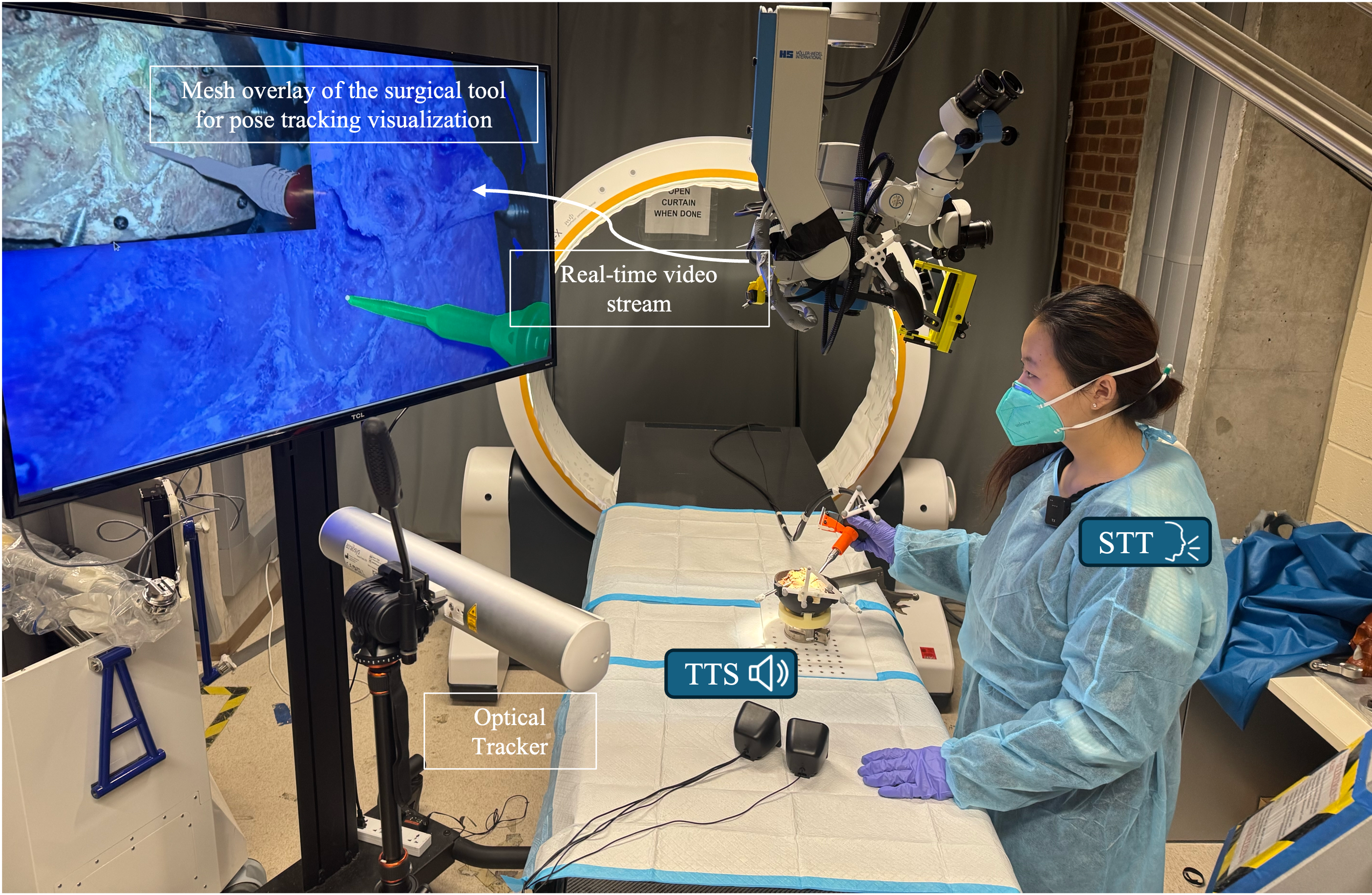
We evaluated the proposed framework in video-guided skull base surgery scenarios using an ex vivo skull-base setup. The surgical drill was tracked concurrently using (i) the optical tracker and (ii) the proposed vision-based perception and pose-tracking pipeline. To enable direct comparison, we time-matched the two data streams and expressed both pose estimates in the same anatomy coordinate frame obtained from the registration procedure.
Across three trials, the user performed continuous tool motion including approach, drilling-like contact motion, and withdrawal. All reported statistics are computed over time-matched frames after initialization and registration, excluding frames where either system produced invalid measurements (e.g., missing optical tracking due to marker dropout).
IV-A Pose Tracking Accuracy
Tool-tip translation error
For each time-matched frame , we obtained the vision tip position by transforming the estimated camera-frame tip into , and we obtained the optical-tracker tip position by applying the measured marker pose and a fixed pivot offset from the marker body to the drill tip. The signed position error in the anatomy frame was computed as
| (3) |
We report per-axis absolute errors and Euclidean error as meanstd across frames for each trial (Table I).
| (mm) | (mm) | (mm) | (mm) | |
|---|---|---|---|---|
| Trial 1 | 1.53 0.67 | 1.37 2.04 | 1.81 0.67 | 2.74 1.74 |
| Trial 2 | 0.72 0.57 | 2.01 1.77 | 0.49 0.52 | 2.32 1.76 |
| Trial 3 | 1.21 0.48 | 1.02 1.84 | 2.73 0.54 | 3.44 1.43 |
| Mean | 1.15 0.57 | 1.47 1.88 | 1.68 0.58 | 2.83 1.64 |
Note: Differences are between the optical tracker and the vision-based method, expressed in the anatomy coordinate frame. Values are mean standard deviation across time-matched frames for each trial.
Inter-frame rotation propagation discrepancy.
Because absolute orientation can depend on convention and initialization, we compare relative inter-frame motion. Let and denote the vision-based and optical-tracker rotations expressed in . We compute per-step increments
| (4) |
and define the per-step propagation discrepancy as
| (5) |
We then extract and report the two incremental rotation components that are orthogonal to the tool axis, based on the validation frame definition (ZYX decomposition of ). Rotation about the tool axis corresponds to shaft spin, which our 5D estimator does not model and is therefore omitted. All rotation statistics are aggregated as meanstd across steps for each trial (Table II).


| (deg) | (deg) | (deg) | |
|---|---|---|---|
| Trial 1 | 0.18 0.24 | 0.13 0.14 | 0.22 0.21 |
| Trial 2 | 0.20 0.26 | 0.24 0.38 | 0.31 0.35 |
| Trial 3 | 0.11 0.13 | 0.14 0.14 | 0.18 0.14 |
| Mean | 0.16 0.21 | 0.17 0.22 | 0.24 0.23 |
Note: Per-step increments are and discrepancy is . Yaw is constrained (shaft spin locked) in the estimator, so we report roll/pitch and the geodesic discrepancy angle .
Discussion.
Across three trials, the proposed vision-based method achieved millimeter-scale agreement with optical tracking in the anatomy frame (Table I) while maintaining low inter-frame rotation propagation discrepancy (Table II). The largest translation deviations occur primarily during fast motion and when the tool undergoes large out-of-plane tilt, which is consistent with increased depth sensitivity and partial visibility.
IV-B Workflow Efficiency
We evaluated workflow efficiency by measuring the user time required for (1) interactive tool segmentation and mask selection and (2) anatomy registration. Each experiment was repeated across multiple trials performed by the same user under consistent conditions. Table III summarizes the recorded times.
On average, tool segmentation and selection required min sec, anatomy registration required min sec, and the complete workflow was completed in min sec.
| Segmentation + Selection | Registration | Total | |
|---|---|---|---|
| Trial 1 | 0 min 26 sec | 1 min 17 sec | 1 min 43 sec |
| Trial 2 | 0 min 27 sec | 1 min 21 sec | 1 min 48 sec |
| Trial 3 | 0 min 25 sec | 1 min 27 sec | 1 min 52 sec |
| Mean Std | 0 min 26 1 sec | 1 min 22 5 sec | 1 min 48 5 sec |
IV-C Case Study on Live Video Stream
To assess usability under realistic operating conditions, we performed a mock surgical study on a live endoscopic video stream in which the user executed the complete pipeline end-to-end: tool segmentation during continuous motion, temporal mask propagation, anatomy segmentation and refinement, anatomy registration, and depth-aware anatomical overlay. Figure 11 shows representative snapshots of the interactive workflow and the resulting registered overlay.
Qualitatively, the system sustained stable tool tracking under moderate occlusions. The on-demand agent interface also allowed the user to transition quickly between segmentation, refinement, and registration without interrupting sterile workflow. Overall, these observations suggest the feasibility of speech-guided, vision-based navigation support for skull-base procedures with minimal setup overhead.
V Conclusion
In this work, we presented an embodied, speech-guided agent framework for video-guided skull base surgery that integrates natural language interaction with real-time visual perception and image-guided navigation. The proposed architecture enables a modular workflow by decoupling reasoning from perception, in which a language-driven planner interprets surgeon intent while specialist vision models execute segmentation, tracking, registration, and pose estimation directly on live endoscopic video streams.
Building upon the prior SCOPE framework, which focused on speech-guided segmentation and tracking, the present work extends the system toward a unified task manager capable of orchestrating multiple perception and navigation functions. The framework enables interactive tool and anatomy segmentation, tool pose estimation, registration, and depth-aware overlays, thereby allowing surgeons to trigger image-guided workflows through natural language queries. Quantitative evaluation demonstrates that the proposed vision-based approach achieves competitive spatial accuracy compared with a commercial optical tracking system while reducing hardware dependence and simplifying workflow integration.
Despite promising results, this study primarily demonstrates technical feasibility in controlled experimental settings, including mock surgical scenarios. The next next step includes evaluating the utility of the system with surgeons. This will include assessing both technical accuracy and task-level outcomes, including time-to-completion, error rates, and interaction efficiency. Additionally, we will incoporate human-centered metrics such as cognitive workload, usability, and perceived workflow compatibility, which will ultimately determine whether the system can effectively function as an intraoperative surgical assistant. Future work will also explore extension to other imaging modalities and surgical procedures. Ultimately, by combining language-guided interaction with real-time surgical perception, the proposed framework represents a step toward scalable, hardware-light intelligent assistants that support surgeons in complex image-guided interventions.
References
- [1] (2023) Artificial intelligence and automation in endoscopy and surgery. Nature Reviews Gastroenterology & Hepatology 20 (3), pp. 171–182. Cited by: §I.
- [2] (2024) VS-assistant: versatile surgery assistant on the demand of surgeons. arXiv preprint arXiv:2405.08272. Cited by: §II.
- [3] (2024) Putting the object back into video object segmentation. In Proceedings of the IEEE/CVF Conference on Computer Vision and Pattern Recognition, pp. 3151–3161. Cited by: §II, §III-A.
- [4] (2022) Core challenges in embodied vision-language planning. Journal of Artificial Intelligence Research 74, pp. 459–515. Cited by: §I.
- [5] (2021) Detection, segmentation, and 3d pose estimation of surgical tools using convolutional neural networks and algebraic geometry. Medical Image Analysis 70, pp. 101994. Cited by: §II.
- [6] (2025) Surgicalvlm-agent: towards an interactive ai co-pilot for pituitary surgery. arXiv preprint arXiv:2503.09474. Cited by: §II.
- [7] (2023) Segment anything. In ICCV, pp. 4015–4026. Cited by: §I, §II, §III-A, §III-C, §III-C.
- [8] (2009) EPnP: an accurate o(n) solution to the pnp problem. In 2009 IEEE 12th International Conference on Computer Vision (ICCV), pp. 1–8. Cited by: §III-D.
- [9] (2024) On the monocular 3-d pose estimation for arbitrary shaped needle in dynamic scenes: an efficient visual learning and geometry modeling approach. IEEE Transactions on Medical Robotics and Bionics 6 (2), pp. 460–474. Cited by: §II.
- [10] (2024) Llava-surg: towards multimodal surgical assistant via structured surgical video learning. arXiv preprint arXiv:2408.07981. Cited by: §I.
- [11] (2023) Tatoo: vision-based joint tracking of anatomy and tool for skull-base surgery. International journal of computer assisted radiology and surgery 18 (7), pp. 1303–1310. Cited by: §III-F.
- [12] (2024) Grounding dino: marrying dino with grounded pre-training for open-set object detection. In ECCV, pp. 38–55. Cited by: §II, §III-A.
- [13] (2025) Surgraw: multi-agent workflow with chain-of-thought reasoning for surgical intelligence. arXiv preprint arXiv:2503.10265. Cited by: §I.
- [14] (2025) SCOPE: speech-guided collaborative perception framework for surgical scene segmentation. In International Workshop on Emerging LLM/LMM Applications in Medical Imaging, pp. 71–78. Cited by: §III-A, §III-B, §III-C.
- [15] (2023) Comprehensive microsurgical anatomy of the middle cranial fossa: Part I—Osseous and meningeal anatomy. Frontiers in Surgery 10. Cited by: §I.
- [16] (2024) SuFIA: language-guided augmented dexterity for robotic surgical assistants. In 2024 IEEE/RSJ International Conference on Intelligent Robots and Systems (IROS), pp. 6969–6976. Cited by: §I.
- [17] (2018) Vision-based surgical tool pose estimation for the da vinci® robotic surgical system. IROS. Cited by: §II.
- [18] (2024) Sam 2: segment anything in images and videos. arXiv preprint arXiv:2408.00714. Cited by: §II.
- [19] (2024) Grounded sam: assembling open-world models for diverse visual tasks. arXiv preprint arXiv:2401.14159. Cited by: §I, §II, §III-A.
- [20] (2024) GSAM+ cutie: text-promptable tool mask annotation for endoscopic video. In CVPR Workshop, pp. 2388–2394. Cited by: §II.
- [21] (2022) Zebrapose: coarse to fine surface encoding for 6dof object pose estimation. In Proceedings of the IEEE/CVF Conference on Computer Vision and Pattern Recognition, pp. 6738–6748. Cited by: §II.
- [22] (2019) CAI4CAI: the rise of contextual artificial intelligence in computer-assisted interventions. Proceedings of the IEEE 108 (1), pp. 198–214. Cited by: §I, §III-F.
- [23] (2024) Video-instrument synergistic network for referring video instrument segmentation in robotic surgery. IEEE Transactions on Medical Imaging. Cited by: §I, §II.
- [24] (2024) FoundationPose: unified 6d pose estimation and tracking of novel objects. In Proceedings of the IEEE/CVF Conference on Computer Vision and Pattern Recognition (CVPR), pp. 17868–17879. Cited by: §III-F.
- [25] (2024) Surgbox: agent-driven operating room sandbox with surgery copilot. In 2024 IEEE International Conference on Big Data (BigData), pp. 2041–2048. Cited by: §II.
- [26] (2024) Depth anything: unleashing the power of large-scale unlabeled data. In Proceedings of the IEEE/CVF conference on computer vision and pattern recognition, pp. 10371–10381. Cited by: §III-C, §III-F.
- [27] (2023) Lisa++: an improved baseline for reasoning segmentation with large language model. arXiv preprint arXiv:2312.17240. Cited by: §II.
- [28] (2024) SurgicalSAM: efficient class promptable surgical instrument segmentation. In Proceedings of the AAAI Conference on Artificial Intelligence, Vol. 38, pp. 6890–6898. Cited by: §II.
- [29] (2023) Text promptable surgical instrument segmentation with vision-language models. NeurIPS 36. Cited by: §I, §II.