Scalable DNA Ternary Full Adder Enabled by a Competitive Blocking Circuit
Abstract
DNA adder circuits are programmable reaction networks that process DNA molecular inputs to compute a sum and serve as essential components for digital computation. Currently, DNA adders primarily focus on binary addition. While efforts extend the operational bit-width by minimizing the number of DNA strands and developing carry-transmission mechanisms, challenges such as the susceptibility of carrying information to attenuation and the limited expressive capacity of the binary system impose significant constraints on computational scale. This paper proposes a scalable ternary adder architecture by introducing an innovative competitive blocking (CB) circuit. The architecture employs a dual cooperative optimization strategy that significantly enhances single-bit computational capacity and incorporates a dynamic concentration adjustment (CA) to effectively broaden the computational bit-width. Consequently, a significant increase in molecular computing scale is achieved compared to previous binary adders. Biochemical experimental results indicate that the CB circuit effectively outputs the ternary full-adder bit and successfully performs 10-bit addition. Furthermore, by implementing the CA strategy, this adder can be further extended to support 17-bit addition. This research provides a novel methodological foundation for advancing DNA computing technologies and offers promising potential for scalable digital computing applications.
keywords:
DNA ternary adder, competitive blocking circuit, concentration adjustment, DNA logic circuits, DNA strand displacement reactionEnqiang Zhu Peize Qiu Xianhang Luo* Chanjuan Liu* Jin Xu
Prof.Enqiang Zhu
Institute of Computational Science and Technology, Guangzhou University, China
Peize Qiu
Institute of Computational Science and Technology, Guangzhou University, China
Dr.Xianhang Luo
School of Computer Science and Technology, Wuhan University of Science and Technology, China
202313601008@wust.edu.cn
Prof.Chanjuan Liu
School of Computer Science and Technology, Dalian University of Technology, China
chanjuanliu@dlut.edu.cn
Prof.Jin Xu
School of Computing Science, Peking University, China
1 Introduction
Molecular systems represent a revolutionary intersection of biology, computing, and engineering, offering unique capabilities that traditional silicon-based systems cannot match [12]. By leveraging the Watson-Crick base-pairing principle, DNA molecules exhibit remarkable programmability at the molecular level, enabling them to evolve into a novel computational paradigm. Since Adleman [1] first employed DNA to solve the traveling salesman problem, DNA computing has attracted significant attention. DNA molecules are no longer seen merely as a carrier of genetic information; it is increasingly utilized as a sophisticated engineering material across various research fields [10], including the development of DNA nanostructures [17, 11, 37], the construction of DNA logic gates [16, 55, 52], and applications in disease detection [3, 51, 35, 50]. DNA computing offers remarkable advantages in parallel processing, which greatly enhances computational efficiency [7, 48, 38].
The DNA strand displacement reaction (SDR) plays a crucial role in DNA computing due to its unique properties. Firstly, it operates spontaneously and stably at room temperature without requiring enzymes [23, 28]. Secondly, SDR demonstrates precise sequence orthogonality, enabling specific interactions among different sequences. This characteristic is essential for constructing complex computational networks, thereby significantly enhancing computational accuracy and reliability [24, 42]. By leveraging SDR technology, researchers have successfully created a range of molecular computing devices [8, 29, 22, 25, 43, 44, 46]. Among them, the “seesaw” gates introduced by Qian and Winfree were the first to realize large-scale digital circuits[33] and neural networks[32], and are now regarded as the cornerstone of scalable strand-displacement logic. Subsequently, DNA tile-based computing [40, 9, 45, 34] and DNA-origami logic circuits [4, 6, 5, 21] have further spatialized and structured computational units, expanding the design dimensions. In addition, studies have focused on suppressing leakage during strand-displacement reactions [36]. These advances provide important theoretical support for the field of DNA computing. Among the various molecular computing devices, the prominence of addition operations is particularly pronounced. Addition serves as the cornerstone of a myriad of digital arithmetic operations, including magnitude comparison [26], multiplication [15, 27], and subtraction [18]. Furthermore, it constitutes a core component of arithmetic modules within digital microprocessors [2], where its performance directly dictates the overall efficiency of the computing system. Consequently, the DNA adder, which exemplifies the construction of fundamental arithmetic operations from DNA logic gates, demonstrates SDR’s profound potential for implementing intricate logical functions at the molecular level, thereby establishing a foundation for DNA computing models for more sophisticated tasks [41].
Early logic gates primarily utilized binary encoding, employing single-stranded DNA as input and optical or electrical signals as output [19, 13]. These pioneering efforts successfully constructed fundamental logic gates, including XOR and AND gates [31]. Then, Li et al. [20] combined these XOR and AND gates to develop a half-adder. However, its complex logic-gate design, which exhibits low integration efficiency, makes the DNA full adder difficult to implement. For this, Su et al. [39] created dual-rail DNA logic gates by paralleling single-rail AND and OR gates, effectively integrating a 1-bit full adder with a 4:1 multiplexer to realize a vital DNA arithmetic logic unit. To further simplify circuit complexity, Wang et al. [43] proposed a strategy based on the principle that “any digital circuit can be represented by a set of equations, with equation terms corresponding to specific switches in the circuit.” This approach employed SDR to create DNA switch circuits for molecular digital computing, using only 20% of the DNA strands compared with dual-rail logic expressions. In addition, some studies have achieved DNA adders by introducing complex structures, such as DNA tetraplexes [14] and DNA origami [41]. However, many molecular designs within these structures face scalability issues that impede effective signal transmission. Although Tandon et al. [40] designed a DNA tile-based calculator capable of performing addition on 6-bit binary numbers, its experimental operation and system design are more complex. To overcome these challenges, Xie et al. [47] designed a scalable DNA full adder using cooperative strand displacement reactions (cSDRs). By developing a dual logic gate capable of simultaneously performing XOR and AND operations, they significantly reduced the number of DNA strands required for the computation. Furthermore, they devised a transmitter based on magnetic beads (MBs) to ensure high-fidelity transmission of the carry signal, enabling effective communication of carry information to the subsequent bit.
Despite the advancements in the scalability of multi-bit adders, they still face a core challenge: carry information attenuation. This is primarily due to inherent signal loss in SDRs and the efficiency limitations of converting current outputs into subsequent inputs, which ultimately restrict the computational scale of multi-bit full adders [47]. To address this challenge, we propose a two-pronged solution: first, we aim to increase the adder radix through the development of -ary systems (), which will reduce the dependence on frequent carry transmissions; second, we introduced a concentration adjustment (CA) strategy aimed at minimizing the need for carry information during computation, which significantly enhances the computational capacity of multi-bit adders. The CA strategy essentially applies the principle of chemical equilibrium, using a "divide and conquer" approach to enable the circuit to regulate reactant concentration ratios, thereby optimizing signal transmission efficiency. Notably, the e-ary numeral system is efficient, requiring fewer inputs to accurately represent a given number (see Supporting Information, Section S3). Additionally, the e-ary system is closely associated with the ternary radix, which motivates our exploration of ternary adders in this paper.
Full adders require flexible handling of carry information, a challenge necessitating precise chemical reaction network design. To address this, our study designed a competitive blocking (CB) circuit to accurately recognize and manage carry information from prior calculations. The core of this circuit lies in its clever utilization of differences in reaction rate constants (e.g., in reactions 1, 2, 3) to enable dynamic selection and blocking of reaction pathways, essentially functioning as a logic control based on chemical kinetics. Biochemical experiments demonstrate that the CB circuit can reliably determine whether a carry occurred in prior computations and rapidly respond by selecting the corresponding reaction path. Furthermore, this research, for the first time, successfully integrated ternary logic with the proposed CA strategy and, based on the CB circuit, designed and implemented a highly scalable DNA ternary full adder. Compared to existing technologies, this study has achieved several significant breakthroughs. Specifically, our implementation of seventeen consecutive carries in ternary form significantly enhances the “scale/strand” metric (the ratio of computational scale to the number of strands used), achieving an improvement of 2,405,552 times compared to the most recent reported four consecutive carries binary DNA adder utilizing DNA circuits (detailed calculations can be found in Supporting Information s1.1). Additionally, biochemical experimental results confirm that our proposed CA strategy ensures our DNA multi-bit ternary adder can be easily adapted for calculations involving even higher bit counts. More importantly, the successful application of this new strategy, based on molecular competitive dynamics (-control) and reactant concentration regulation (chemical equilibrium), provides novel insights and tools for designing and constructing more complex and robust chemical reaction-based molecular systems.
2 RESULTS AND DISCUSSION
2.1 The Competitive Blocking Circuit
The principle of the CB circuit is illustrated in Figure 1. It consists of two logic gates, denoted and , representing two levels of reaction. The CB circuit has two input signals, denoted as and , along with a blocking signal . The signal can be in a logic state of either or , indicating whether it participates in the reaction. Here, represent the ternary numbers involved in the addition operation. When is in the state, the CB circuit receives and as inputs, activating the first level of reaction. This means that the two inputs interact with to produce an output signal, denoted as SUM1. Conversely, when is , it reacts with , effectively consuming and thereby inhibiting the first level of reaction between and the inputs and . Furthermore, the presence of can activate the second level of the reaction, leading to a reaction with and producing a different output signal, denoted as SUM2.

The CB mechanism can be expressed via the following reactions:
| (1) |
| (2) |
| (3) |
Specifically, is a stable structure formed through base pairing in the , , and domains, while the toehold sites and remain exposed. The strand contains the toehold and the long domain . The toehold of initiates an SDR by pairing with the site on and continues base pairing until the strand incorporating , , and is displaced (The short domain will break free because the two longer domains and are in a free state). As a result, the site becomes exposed. Since contains the toehold and the long domain , it undergoes a similar SDR by pairing with the site, thus displacing the fluorescently labeled single strand . This indicates the generation of SUM1. This process is described by Equation 1 and illustrated in Figure 1.
The blocking strand contains the toehold along with the long domains and . The toehold binds to the site of , effectively locking it through the complementary base pairing principle of DNA (Equation 2 and Figure 1). Given that the toehold comprises only five bases, there is a risk of detachment after locking solely by this interaction. To mitigate this risk, we have added domain to the 5’ end of domain to enhance the stability of ’s binding to , ensuring that the toehold remains firmly locked. We conducted an evaluation of the binding stability of to both before and subsequent to the addition of domain . The results indicate that exhibits a higher binding efficacy with following the incorporation of domain (see Supporting Information S4). This design effectively prevents the toehold in from engaging in an SDR with the site of the gate structure, thereby ensuring that the output strand modified with fluorescence is not displaced. Upon locking , the reaction proceeds with . is a stable structure formed through base pairing in the domain, while the toehold site remains exposed. The blocking strand engages in an SDR with the exposed toehold site of (Equation 3 and Figure 1), leading to the displacement of the output strand that carries the fluorescence modification. The resulting computational output, SUM2, can be determined by analyzing the fluorescent signal.
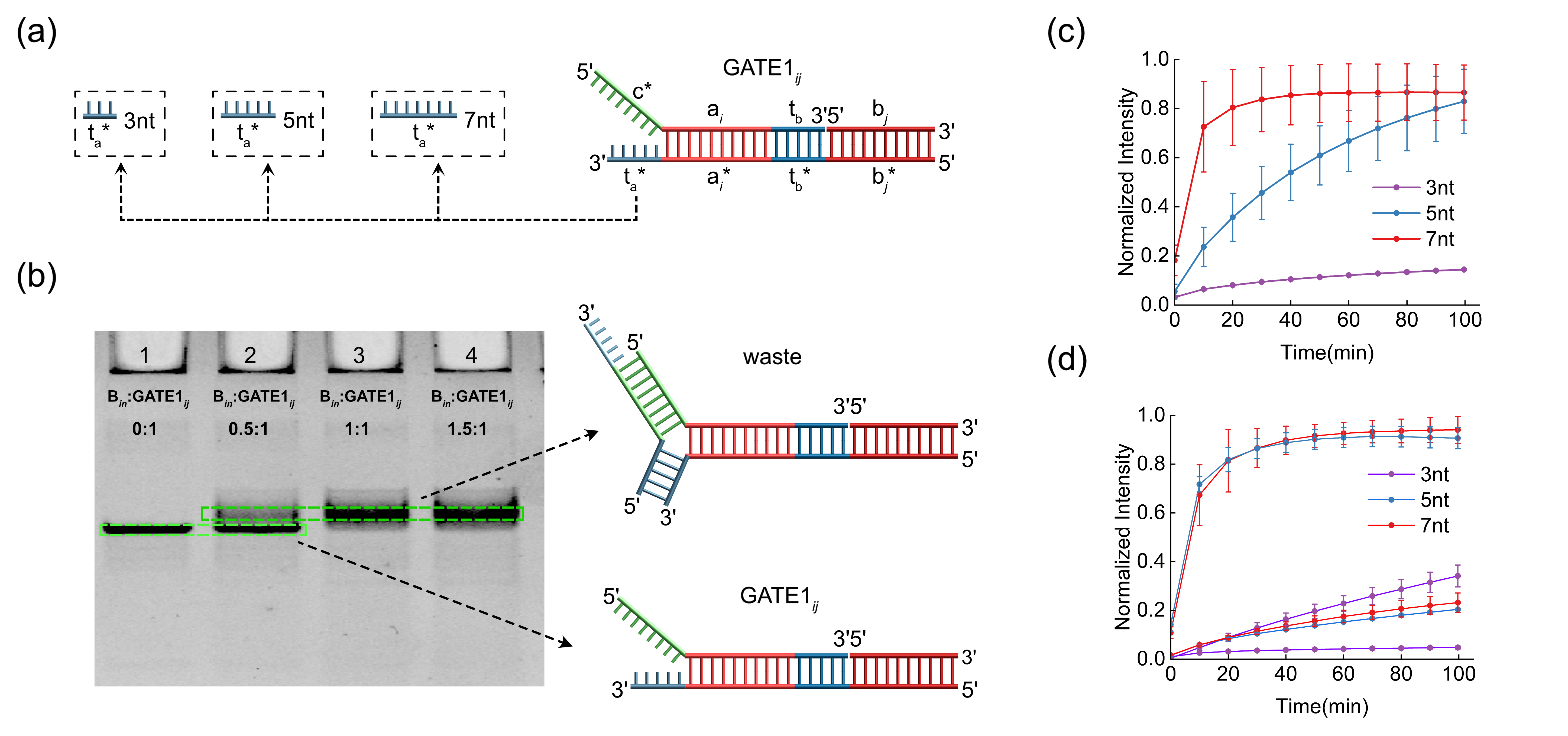
The length of the toehold is pivotal in determining the rate of the SDR [53, 49]. We evaluated the effect of three common toehold lengths of 3nt, 5nt, and 7nt on our reaction rates (Figure 2a). The fluorescence data (Figure 2c) indicate that with a 3nt toehold, the increase in fluorescence intensity is minimal, reflecting a low reaction efficiency. In contrast, extending the toehold length to 5nt and 7nt markedly accelerates the reaction rate, achieving a peak within 30 minutes. Therefore, we excluded the 3nt toehold from further consideration. Additionally, the binding efficiency of to affects the accuracy of the first-level reaction, as a portion of it still occurs even when is present. We call this a leakage reaction. To address this, we examined SUM1 leakage across different toehold lengths. The experimental findings are illustrated in Figure 2d. On the one hand, when using a 3nt toehold, the fluorescence of the leakage reaction producing SUM1 is minimal; however, SUM2 formation is too slow. On the other hand, although the reaction with a 7nt toehold is faster than that with a 5nt toehold, it results in greater leakage of the incorrect result SUM1. Consequently, we opted for a 5nt toehold length to minimize the generation of leakage reaction.
Based on the experimental results for a toehold length of 5 nucleotides, as presented in Figure 2c and Figure 2d, the rates of critical reactions within the CB circuit are detailed as follows. The rate of Reaction 1 (Equation1, which is where and interact with ) is measured at /s. In comparison, the rate of Reaction 2 (Equation2, which is where binds to ) is significantly higher at /s, while the rate of Reaction 3 (Equation3, which is where interacts with ) stands at /s. Further details on the calculation of these rates are provided in Supporting Information S1.2. These results clearly indicate that the reaction rate of Reaction 2 is substantially greater than that of Reaction 1 and 3. This suggests that in the presence of , it will preferentially and rapidly bind to , effectively inhibiting Reaction 1. Following this, proceeds to react with . Conversely, when is absent, the CB circuit will proceed with Reaction 1. Additionally, to verify whether the successfully locks the gate, we examined the binding between and at varying concentrations. Polyacrylamide gel electrophoresis (PAGE) was performed; the results are shown in Fig. 2b. From left to right, the molar ratios of to are 0:1, 0.5:1, 1:1, and 1.5:1. Evidently, when is present it binds efficiently to . In lane 2, a fraction of remains unbound because the concentration is lower than that of . When the concentration is equal to or exceeds that of , all molecules are bound by . We therefore conclude that can effectively bind to .
Moreover, we experimentally demonstrated the robustness of the CB circuit to sequence design choices and its tolerance to noise. First, we tested the stability of the CB circuit under different sequences. A total of nine distinct scenarios were examined, corresponding to the nine input– combinations of the ternary full adder (Figure S17). Subsequently, we tested the effect of on the CB circuit under varying GC content conditions (see Section S5 of the Supporting Information). The results indicate that the CB circuit consistently produces correct outputs across these varied sequences. Second, we evaluated the circuit’s stability in the presence of noise such as mismatches and unrelated strands (see Section S5 of the Supporting Information). The findings confirm that the CB circuit remains functional and yields accurate results even under noisy conditions.
2.2 A Ternary DNA Full Adder Design Using CB Circuit
The design of the ternary full adder, based on the CB circuit, comprises four key components: converting input digits into DNA strands, computing the sum and carry, translating output signals into results, and extracting carry information as input to the next bit. Each bit’s input and output in a ternary adder can take three possible values (0, 1, or 2). This makes the conventional dual-rail strategy difficult to apply [39]. To address this, we employed a triple-rail method to represent the three input and output states. Specifically, we designate , , and to convey the inputs for 0, 1, and 2, while utilizing , , and for similar representations. Each consists of a toehold and domain , and each comprises a toehold and domain , where . Additionally, we employ three distinct fluorescent signals (ROX, FAM, VIC) to visualize the resulting outputs corresponding to 0, 1, and 2. It’s worth noting that the fluorescent signal types assigned to each module’s and follow a specific pattern, with further details provided in Table 4 of Section S15 in the Supporting Information.

Compared to traditional binary adders, the number of input combinations involved in this computation process differs significantly. The input combinations for a traditional binary adder amount to possibilities, as its inputs are limited to two states: 0 and 1. This simplicity enables straightforward implementation using conventional circuits. In contrast, the ternary adder presents a much more complex scenario; it features up to input combinations (see Figure 3a), which poses significant challenges for implementation using standard circuits. To address this complexity, we modularize the design into nine distinct modules, termed -modules (where ), inspired by the principles of computer memory addressing. Based on the CB circuit, these -modules are capable of computing (where is 0 or 1, representing the presence or absence of carry information), thereby generating the result information SUM1 or SUM2 (Figure 3b and Supporting Information, Figure S7 - S15).
According to the truth table (Figure 3a), there are nine scenarios that result in carry information. We categorize these scenarios into two types for processing.
The first type involves carry generation through a three-input AND gate. This includes cases 6, 10, and 14, where a carry is generated only in the presence of (the carry input from the previous bit). This indicates that the production of carry information relies on the inputs , , and . Consequently, we implement this function using a three-input AND gate (, where , as illustrated in Figure 4a). The structure of comprises four single strands, which stabilize through base pairing in the toehold regions and , along with the longer domains , , and . At the same time, it reveals the toehold site and the longer domain . When all three inputs, , , and , are present, this gate produces the carry information strand . The specific reaction mechanism is depicted in Figure 4a. Initially, the toehold of binds to the exposed toehold of . This interaction facilitates the engagement of the long domain of with the domain within , leading to the release of domain from . As consists of only five bases, the strand will subsequently detach once domain is liberated, thereby exposing the toehold . Subsequently, a parallel reaction will displace the strand upon the introduction of , which in turn reveals the toehold . At this juncture, if the carry information from the previous bit is present, it will bind to the exposed toehold and displace the information strand through an SDR.
The second type involves carry generation through a two-input AND gate in conjunction with a conversion gate. This category includes cases 11, 12, 15, 16, 17, and 18. In these scenarios, a carry is generated for the subsequent bit regardless of the carry input . This indicates that the carry information relies exclusively on and . We implement this function using a two-input AND gate (, where (see Figure 4b)). The structure of consists of three single strands stabilized through base pairing at the toehold , along with the longer domains and . It also features the toehold site and a longer domain . When both and are present, this gate produces an output. The specific reaction mechanism is illustrated in Figure 4b. Similar to the first type, when and are both present, the strands and are sequentially displaced. It is important to highlight that this reaction does not directly yield the carry information strand ; instead, it produces an intermediate strand . To resolve this issue, we devised a conversion gate for (as shown in Figure 4b). The structure of - consists of two single strands, one of which contains the necessary carry information. These strands are stabilized through base pairing involving their domain . Furthermore, the gate includes a toehold site and a domain . When the intermediate strand is available, this gate will produce an output, effectively transforming into the carry information strand for subsequent extraction processes.
To extract the carry information and transfer it to the subsequent bit calculation, we designed an extractor referred to as GATE-Extract (Figure 4c). This structure forms a hairpin shape through self-complementary base pairing between the domains and , with the toehold embedded within the hairpin. As shown in Figure 4c, when the carry information is present in the test tube, the domain of the hairpin engages in an SDR with the domain of the information strand . This reaction opens the hairpin structure, revealing the toehold and the extended domain . The GATE-Extract is modified with a biotin group at the 5’ end. By leveraging the strong affinity between streptavidin MBs and biotin, - is anchored to the MB surface, thereby completing the extraction of the carried information.
2.3 An implementation of Ternary DNA Half-Adder and 1-Bit Full Adder Using CB circuit
A ternary half-adder is designed to add two ternary digits, producing two outputs: a sum and a carry . This operation is performed without considering carry information. To calculate the sum of two inputs, and , we utilize the -module. Let’s examine the case where and . Notably, other cases follow a similar method. In our implementation, and are introduced into the -module. These inputs interact with , resulting in the gradual displacement of the strand from . Since the 3’ end of strand is modified with a FAM fluorescent group, and the bottom strand of is equipped with a BHQ1 quencher group, the FAM signal is triggered upon the displacement of strand . This results in an value of 1, as illustrated in Figure 3c, curve 22. Concurrently, and in the test tube participate in an SDR with (Figure 4b), which displaces the strand . Subsequently, the strand interacts with - to produce the Carry strand. In addition to the experiment described above, we also tested the other eight input combinations using -modules for , where . The fluorescence output of each module matches the expected result (Figure 3c and Supporting Information, Figure S16), further validating the reliability of the ternary half-adder design.

We constructed a 1-bit full adder using our CB circuit. In comparison to the half-adder, the full adder includes an additional Carry input, , from the previous bit, making it a third input. This circuit also produces two outputs: a sum and a carry . We employed the -module to compute the addition of two addend inputs alongside the carry input (serving as the blocking strand). For illustrative purposes, we set and ; other cases can be treated similarly. The implementation involves four logic gates: , , , and . Specifically, the CB circuit allows to block the toehold domain of (Equation 2), preventing it from reacting with and . At the same time, engages in strand displacement with (Equation 3), resulting in the release of the strand labeled with a VIC fluorophore at its 3’ end. The detection of this VIC fluorescence signal indicates that . Concurrently, and undergo strand displacement with (Figure 4b), releasing the strand , which then interacts with to ultimately generate the carry . Experimental results show that effectively blocked , limiting the fluorescence intensity of the leakage reaction between and with to below 0.5 (Figure 3e). This mechanism, which redirects the reaction to and , yielded VIC fluorescence output corresponding to the correct result 2 (Supporting Information, Figure S17). In addition to the aforementioned experiments, we also evaluated the other eight input combinations using -modules (where and ). Each of these combinations successfully generated a fluorescence signal indicating the correct output (Figure 3d and Supporting Information, Figure S17). Furthermore, in contrast to the half-adder (where outputs were exclusively SUM1 result information), when is present, all input combinations yielded SUM2 result information. Crucially, the corresponding SUM1 result information (generated by the leakage reaction) consistently remained below half of the SUM2 result information (Figure 3e). To further analyze the absolute output and absolute leakage for each input combination under the presence of , we normalized all fluorescence signals (including both valid outputs and leakage signals) relative to the highest fluorescence value. The experimental results show that the normalized SUM1 leakage signal intensity remains consistently below half of the SUM2 output signal intensity. (see Section S9 of the Supporting Information) This decisively demonstrates the effectiveness of the CB circuit in the adder.
2.4 The Implementation of Multi-bit Ternary DNA Full Adder Using CB Circuit
To effectively manage the propagation of carry information for each bit in a multi-bit adder, we utilized streptavidin MBs to extract and transfer carry information. Streptavidin is a protein known for its exceptional binding affinity to biotin [30, 54]. Since the carry information strand is not the strand required for subsequent carry propagation, we designed an amplification-and-conversion reaction (Figure 5a). First, GATE-amplifier transforms the Carry Carrier (CC) into strands. Then, to compensate for signal loss inherent in SDR and for losses during magnetic-bead extraction and transfer, we introduce fuel strands that further react with the intermediate strand generated from CC and GATE-amplifier, regenerating CC and thereby cyclically producing more strands for downstream carry calculations. Experiments show that this amplification reaction increases strand yield by approximately threefold (see Section S10 of the Supporting Information). The specific procedure is detailed below: The completed computational system is positioned on a magnetic rack, where - bound to streptavidin MBs is attracted to the bottom of the test tube via magnetism. After removing the supernatant (which contains unneeded waste), - and fuel strands are introduced. During experiments, it was observed that even in the absence of , a fluorescent signal was still produced. The reason this happened is that the -, intended for signal amplification, can react similarly to , though with lower efficiency. To mitigate this issue, we modified the 5’ end of the single strand located below - with biotin. After signal amplification, we again placed the reaction system on a magnetic rack, thereby drawing the to the bottom of the test tube. Following this, the supernatant was collected as the input for the next bit. This approach prevents misrecognition and ensures the accurate transfer of carry information.

To evaluate the feasibility of the multi-bit ternary full adder, we conducted an operational test using a ten-bit ternary full adder, focusing on the addition . The procedure began by adding and to the designated test tube for the 12-module, followed by measurement of the resulting bit’s fluorescent signal. Subsequently, carry information was extracted through magnetic selection and subjected to a signal amplification reaction. After another round of magnetic selection, the supernatant was transferred to the next bit calculation module along with the next bit’s inputs ( and ). The output from the fluorescent reporter gate was then recorded. This process continued until all bit calculations were complete (Figure 5b). Additionally, to enable an intuitive comparison of leakage rates at each bit, we predetermined the fluorescence intensity ratios among the three dyes through 15 independent experiments (see Section S11 of the Supporting Information) and uniformly normalized all subsequent data accordingly. The results are illustrated in Figure 5c, where the green, orange, and blue curves correspond to the fluorescence signals of ROX, FAM, and VIC, representing values of 0, 1, and 2, respectively. For each bit, the number indicated by the fluorescence species with the maximum fluorescence value (where all other fluorescence readings fall below half of this maximum) is deemed the final result for that bit. The overall result presented in the figure is , thereby confirming both the feasibility and accuracy of the design.
To rigorously evaluate the scalability of the CB-circuit-based ternary adder, we adopted “consecutive carry capability” as the key metric. Should consecutive carries terminate, the strand concentration is reset, and the true scalability is masked; hence, the upper limit of consecutive carries directly determines the scalability boundary. We thus designed a full consecutive-carry test: the adder achieves 100 % success for up to eight consecutive carries, whereas success drops to 33.33 % when consecutive carries reach the 9th and 10th bits (Figure 5d). Restricting our analysis to 100 % successful cases, we conclude that the consecutive-carry capability of the CB ternary adder is eight bits.
2.5 Experimental Expansion of Bit Positions for the Multi-bit DNA Ternary Full Adder
Due to the inherent limitations of biological experiments, multi-bit DNA adders face a core challenge during actual operation: as the number of consecutive carry bits increases, the quantity of the carry information strand progressively diminishes, leading to computational errors. This is the fundamental reason impacting the scalability of DNA adders. Our design addresses this challenge by decoupling the computation of the result bit from that of the carry. The CA strategy allows us to enhance the performance by adjusting the concentration ratios of the relevant components. In particular, reducing the concentration of enables it to be more effectively bound by (the carry generated from the previous bit), thereby minimizing signal leakage.
To validate this finding, we compared the experimental results from two different concentration configurations: 1) a concentration of 1 M and a concentration of 0.4 M; and 2) a concentration of 1 M and a concentration of 0.2 M. The results, illustrated in Figure 5d, indicate that with the higher concentration of in the first case, the carry information from the preceding bit must block more molecules, leading to a decrease in the amount of carry information available for carry calculation. Consequently, as the number of bits increases, the carry information exhibits a trend of accelerated attenuation, which in turn results in a significant reduction in the carry information contributing to the sum bit calculation. The fluorescence signal for the sum bit decays notably faster in this scenario compared to the second case. Note that even without the introduction of the CA strategy, we could still achieve eight consecutive carry calculations (Figure 5d). This is because our judgment was based on the maximum fluorescence value of each bit, requiring other fluorescence values to be less than half of the maximum. Therefore, even as the information continuously decayed, the leakage rate(i.e., the ratio of the maximum fluorescence value corresponding to non-maximal fluorescence types to the maximum fluorescence value) remained below 0.5, allowing us to perform consecutive multi-bit carry calculations. Based on this, we further evaluated the change in leakage rate as the number of bits increased following the introduction of the CA strategy. The results show that the leakage rate was significantly reduced after the introduction of the CA strategy (Figure 5d and Figure 5e). Additionally, the CA strategy helps to reduce signal attenuation. In particular, as the bit count increases, the adder employing the CA strategy demonstrates a slower decay rate in the fluorescence signal that indicates the correct result (see Figure 5d) compared to the adder that does not utilize the CA strategy (see Figure 5e). This strongly demonstrates the effectiveness of our proposed CA strategy.
To assess the practical upper limit of the CA strategy, we performed a seventeen consecutive carry ternary addition and successfully achieved the correct output. However, the 18th carry failed because the leakage rate exceeded the detection threshold, thereby establishing the maximum reliable depth of the current system at 17 carries (see Figure 5e). Additionally, we examine in detail the applicability of the CA strategy in Section S13 of the Supporting Information. This represents a significant advancement over current state-of-the-art multi-bit adders based on DNA circuits, which have only achieved four consecutive carries. In terms of the realized scale, our achievement is 2405552 times greater than that reported in recent studies (detailed calculations are provided in Supporting Information s1.1). This finding provides a promising direction for future design optimization of higher-bit full adders.
To intuitively illustrate the scalability advantage provided by the higher radix, we first developed 9-bit binary and 8-bit ternary full adders (all featuring consecutive carries) within the same CB-circuit core architecture. As depicted in Figure 5d and Figure S23, both types operate with a comparable bit count, yet the computational capability of the binary adder is only about 7.79% that of the ternary adder (refer to Supporting Information S12 for further details). Additionally, utilizing the CA strategy, we constructed 17-bit binary and 17-bit ternary full adders (also with consecutive carries). The experimental outcomes presented in Figure 5e and Figure S24 demonstrate that both adders once again maintain the same bit count; however, the computational scale of the binary adder is a mere 0.1% of that of the ternary adder (see Supporting Information S12 for more details). These two adders achieve comparable bit depths, as the per-bit signal attenuation is similarly aligned under the identical CB/CA core architecture (as illustrated in Figures S25 and S26). Thus, within the same framework, the ternary implementation clearly offers a significant advantage.
3 CONCLUSIONS
This paper first introduces a chemically kinetic logic control circuit (CB circuit). It cleverly leverages differences in reaction rate constants to enable the dynamic selection and blocking of reaction pathways. Second, by applying the principles of chemical equilibrium, we propose a CA strategy based on a divide-and-conquer approach. This strategy empowers the circuit to regulate reactant concentration ratios, thereby optimizing signal transmission efficiency. Subsequently, these two innovations have led to the successful realization of a highly scalable ternary DNA full adder. This innovative ternary DNA adder significantly addresses the computational scale limitations of traditional DNA adders, achieving a scale that far surpasses existing methodologies based on DNA circuit. The experimental results show that the maximum computational scale achievable by the DNA adder with consecutive carries has been extended by approximately times, representing a significant enhancement. While achieving infinite carry propagation remains a challenge, the experimental findings fully demonstrate the validity and efficiency of our approach.
Although we have not yet directly characterized addition circuits beyond seventeen consecutive carries, several strategies can further extend scalability: (i) introducing additional leakage-filter modules or lower-leakage strand-displacement schemes (e.g., using clamps in the seesaw circuits); (ii) fine-tuning the CA strategy to further strengthen the carry-information strand; (iii) circuit optimization, such as employing enzymes to achieve more efficient strand displacement and thus reduce signal attenuation; and (iv) spatial localization, anchoring computational modules at distinct locations (e.g., specific sites on DNA origami or on separate magnetic beads/nanoparticle surfaces) to prevent signal molecules from diffusing throughout the bulk solution, minimize crosstalk, and ensure that signals are delivered to neighboring modules along predefined paths. Collectively, these approaches provide a clear roadmap for pushing the DNA ternary-adder architecture beyond the current experimentally demonstrated number of carry bits.
The realization of a scalable ternary DNA full adder represents a significant advancement in biomolecular computing. Our research not only enhances computational capabilities but also helps reduce costs, making DNA computing more practical and sustainable. Additionally, the CB circuit can process multiple input signals based on their priority, providing a powerful tool for developing more complex DNA computing systems. This also highlights the immense potential of DNA computing in advancing the chemistry of molecular information processing. Moreover, the CA strategy and the module partitioning method provide a new perspective for reducing the impact of leakage reactions on circuit performance. More importantly, the successful application of the CB circuit and CA strategy provides new insights and tools for designing and constructing more complex and robust chemical reaction-based molecular systems, extending beyond computation to areas such as sensing, diagnostics, and drug delivery control.
To develop a more intelligent, automated ternary multi-bit full adder, we aim to integrate microfluidic technology with other techniques. This integration will enable the immobilization of magnetic beads within microchannels and achieve fully automated, continuous addition operations through programmed valve‑based flow switching. The ternary full adder has the potential to optimize the performance of complex systems and may offer unique advantages in areas such as artificial intelligence, neural networks, and cryptography in the future.
4 Experimental Section
4.1 Materials
DNA oligonucleotides were purchased from Sangon Biotech (Shanghai) Co., Ltd. and purified by high-performance liquid chromatography (HPLC). All DNA strand sequences used in biochemical experiments were initially designed using NUPACK and subsequently manually optimized to ensure GC content remained between 30% and 60%. The full list of sequences used in this study is provided in Table 3 of Section S14 in the Supporting Information. Unmodified DNA strands were dissolved in TE buffer and stored at . Fluorescently labeled or quencher-modified strands were dissolved in deionized water and stored at in the dark. DNA concentrations were measured using a NanoPhotometer N120. Prior to experiments, DNA samples were prepared by mixing with 12.5 mM in TE buffer.
The DNA complexes were assembled by mixing equimolar amounts of the corresponding single-stranded DNA oligonucleotides and then annealing in a PCR thermocycler. The annealing protocol consisted of an initial denaturation at for 2 min, followed by a gradual cooling: from to at a rate of every 3s, then to at every 6s, and finally to at every 3s. The annealed complexes were stored at for subsequent use. For fluorescently labeled or quencher-modified complexes, the cooling rate after the initial denaturation (, 2 min) was set to every 6s down to , after which the samples were stored at until use.
4.2 Fluorescence Kinetics Experiments
In fluorescence-kinetics assays, the target DNA concentration was inferred from the measured fluorescence intensity. DNA samples were prepared according to the experimental design, with 1 defined as 1 . Final concentrations corresponded to 2 input gate and 1 reaction gate. Fluorescence was monitored using a QuantStudio 3&5 Real-Time PCR System (Thermo Fisher Scientific, Waltham, MA, USA) equipped with a 96-well fluorescence plate reader. The thermal profile was set as follows: during the holding stage, the temperature was decreased to at /s and held for before the PCR stage; subsequently, the temperature was ramped up to at /s, and fluorescence readings were acquired every . All fluorescence curves were normalized to allow for direct comparison across experiments.
4.3 Statistical Analysis
Normalization method: Fluorescence correction was performed via 15 independent experiments—under identical circuit and sequence conditions, single-dye reactions (ROX, FAM or VIC) were run in full, the intensity of each dye was recorded in all three channels, and the brightest ROX was set as reference (1.00) to yield the correction ratio ROX:FAM:VIC = 1.00:0.939:0.261; all subsequent readings were corrected by these factors. Normalization formula: . Data presentation: Results are shown as mean SD; consecutive-carry experiments used two replicates, whereas data from the half-adder and one-bit full adder are plotted using a single dataset; all remaining experiments used three replicates. Statistical analyses were carried out with OriginPro 2024.
Supporting Information
Supporting Information is available from the Wiley Online Library or from the author.
Acknowledgements
This work was supported by the National Major Scientific Instrument and Equipment Development Project of the National Natural Science Foundation of China (No. 62427811) and the National Natural Science Foundation of China (No. 62272115). The authors declare no competing financial interest.
References
- [1] (1994) Molecular computation of solutions to combinatorial problems. science 266 (5187), pp. 1021–1024. Cited by: §1.
- [2] (2010) CMOS full-adders for energy-efficient arithmetic applications. IEEE transactions on very large scale integration (VLSI) systems 19 (4), pp. 718–721. Cited by: §1.
- [3] (2018) Global surveillance of trends in cancer survival 2000–14 (concord-3): analysis of individual records for 37 513 025 patients diagnosed with one of 18 cancers from 322 population-based registries in 71 countries. The Lancet 391 (10125), pp. 1023–1075. Cited by: §1.
- [4] (2014) Universal computing by dna origami robots in a living animal. Nature nanotechnology 9 (5), pp. 353–357. Cited by: §1.
- [5] (2018) Localized dna hybridization chain reactions on dna origami. ACS nano 12 (2), pp. 1146–1155. Cited by: §1.
- [6] (2017) A spatially localized architecture for fast and modular dna computing. Nature nanotechnology 12 (9), pp. 920–927. Cited by: §1.
- [7] (2023) DNA strand displacement based computational systems and their applications. Frontiers in Genetics 14, pp. 1120791. Cited by: §1.
- [8] (2010) DNA computing circuits using libraries of dnazyme subunits. Nature nanotechnology 5 (6), pp. 417–422. Cited by: §1.
- [9] (2017) Physical principles for dna tile self-assembly. Chemical Society Reviews 46 (12), pp. 3808–3829. Cited by: §1.
- [10] (2020) Propelling dna computing with materials’ power: recent advancements in innovative dna logic computing systems and smart bio-applications. Advanced Science 7 (24), pp. 2001766. Cited by: §1.
- [11] (2017) Sensing of dangerous dna. Mechanisms of ageing and development 165, pp. 33–46. Cited by: §1.
- [12] (2019) High-performance biocomputing in synthetic biology–integrated transcriptional and metabolic circuits. Frontiers in bioengineering and biotechnology 7, pp. 40. Cited by: §1.
- [13] (2018) 8-bit adder and subtractor with domain label based on dna strand displacement. Molecules 23 (11), pp. 2989. Cited by: §1.
- [14] (2019) Versatile and homogeneous dna tetraplex platform for constructing label-free logic devices: from design to application. Chemistry–A European Journal 25 (28), pp. 6996–7003. Cited by: §1.
- [15] (2017) Fast bit-parallel binary multipliers based on type-i pentanomials. IEEE Transactions on Computers 67 (6), pp. 898–904. Cited by: §1.
- [16] (2023) Three-input logic gate based on dna strand displacement reaction. Scientific Reports 13 (1), pp. 15210. Cited by: §1.
- [17] (2018) The detection of a mismatched dna by using hairpin dna-templated silver nanoclusters. Analytical Biochemistry 549, pp. 171–173. Cited by: §1.
- [18] (2012) Low-power logarithmic number system addition/subtraction and their impact on digital filters. IEEE Transactions on Computers 62 (11), pp. 2196–2209. Cited by: §1.
- [19] (2015) Implementation of arithmetic functions on a simple and universal molecular beacon platform. Advanced Science 2 (5), pp. 1500054. Cited by: §1.
- [20] (2016) DNA based arithmetic function: a half adder based on dna strand displacement. Nanoscale 8 (6), pp. 3775–3784. Cited by: §1.
- [21] (2025) Programming directional strand polymerization on dna origami for logic computing. Small Structures, pp. 2500220. Cited by: §1.
- [22] (2020) Cross-inhibitor: a time-sensitive molecular circuit based on dna strand displacement. Nucleic acids research 48 (19), pp. 10691–10701. Cited by: §1.
- [23] (2017) Regulating dna self-assembly by dna–surface interactions. ChemBioChem 18 (24), pp. 2404–2407. Cited by: §1.
- [24] (2021) Biocomputing based on dna strand displacement reactions. ChemPhysChem 22 (12), pp. 1151–1166. Cited by: §1.
- [25] (2023) DNA-based programmable gate arrays for general-purpose dna computing. Nature 622 (7982), pp. 292–300. Cited by: §1.
- [26] (2013) 2-bit comparator using different logic style of full adder. Int. J. Soft Comput. Eng. IJSCE 3, pp. 277–9. Cited by: §1.
- [27] (2009) Two new low-power full adders based on majority-not gates. Microelectronics journal 40 (1), pp. 126–130. Cited by: §1.
- [28] (2018) Comparative study of dna circuit system-based proportional and exponential amplification strategies for enzyme-free and rapid detection of mirna at room temperature. ACS omega 3 (3), pp. 3321–3329. Cited by: §1.
- [29] (2014) A full-adder based on reconfigurable dna-hairpin inputs and dnazyme computing modules. Chemical Science 5 (9), pp. 3381–3387. Cited by: §1.
- [30] (2017) The role of ch/ interactions in the high affinity binding of streptavidin and biotin. Journal of Molecular Graphics and Modelling 75, pp. 117–124. Cited by: §2.4.
- [31] (2012) Simple and universal platform for logic gate operations based on molecular beacon probes. Small 8 (14), pp. 2203–2212. Cited by: §1.
- [32] (2011) Neural network computation with dna strand displacement cascades. nature 475 (7356), pp. 368–372. Cited by: §1.
- [33] (2011) Scaling up digital circuit computation with dna strand displacement cascades. science 332 (6034), pp. 1196–1201. Cited by: §1.
- [34] (2023) Modular reconfiguration of dna origami assemblies using tile displacement. Science Robotics 8 (77), pp. eadf1511. Cited by: §1.
- [35] (2020) Advances in the genetic testing of neuromuscular diseases.. Neurologic Clinics 38 (3), pp. 519–528. Cited by: §1.
- [36] (2018) Improving the performance of dna strand displacement circuits by shadow cancellation. ACS nano 12 (11), pp. 11689–11697. Cited by: §1.
- [37] (2021) The binding of monoclonal and polyclonal anti-z-dna antibodies to dna of various species origin. International Journal of Molecular Sciences 22 (16), pp. 8931. Cited by: §1.
- [38] (2025) A thermodynamically favoured molecular computer: robust, fast, renewable, scalable. bioRxiv, pp. 2025–07. Cited by: §1.
- [39] (2019) High-efficiency and integrable dna arithmetic and logic system based on strand displacement synthesis. Nature communications 10 (1), pp. 5390. Cited by: §1, §2.2.
- [40] (2020) Demonstration of arithmetic calculations by dna tile-based algorithmic self-assembly. ACS nano 14 (5), pp. 5260–5267. Cited by: §1, §1.
- [41] (2025) A localized scalable dna logic circuit system based on the dna origami surface. International Journal of Molecular Sciences 26 (5), pp. 2043. Cited by: §1, §1.
- [42] (2023) Parallel molecular computation on digital data stored in dna. Proceedings of the National Academy of Sciences 120 (37), pp. e2217330120. Cited by: §1.
- [43] (2020) Implementing digital computing with dna-based switching circuits. Nature communications 11 (1), pp. 121. Cited by: §1, §1.
- [44] (2022) Cooperative branch migration: a mechanism for flexible control of dna strand displacement. ACS nano 16 (2), pp. 3135–3144. Cited by: §1.
- [45] (2019) Diverse and robust molecular algorithms using reprogrammable dna self-assembly. Nature 567 (7748), pp. 366–372. Cited by: §1.
- [46] (2024) Plug-and-play module for reversible and continuous control of dna strand displacement kinetics. Journal of the American Chemical Society 146 (10), pp. 6516–6521. Cited by: §1.
- [47] (2022) Scaling up multi-bit dna full adder circuits with minimal strand displacement reactions. Journal of the American Chemical Society 144 (21), pp. 9479–9488. Cited by: §1, §1.
- [48] (2022) Graph computation using algorithmic self-assembly of dna molecules. ACS Synthetic Biology 11 (7), pp. 2456–2463. Cited by: §1.
- [49] (2025) Dna coding theory and algorithms. Artificial Intelligence Review 58 (6), pp. 178. Cited by: §2.1.
- [50] (2021) DNA logic circuits for multiple tumor cells identification using intracellular microrna molecular bispecific recognition. Advanced healthcare materials 10 (21), pp. 2101130. Cited by: §1.
- [51] (2019) Cell-free dna testing: future applications in gastroenterology and hepatology. Therapeutic Advances in Gastroenterology 12, pp. 1756284819841896. Cited by: §1.
- [52] (2023) Implementing logic gates by dna crystal engineering. Advanced Materials 35 (33), pp. 2302345. Cited by: §1.
- [53] (2009) Control of dna strand displacement kinetics using toehold exchange. Journal of the American Chemical Society 131 (47), pp. 17303–17314. Cited by: §2.1.
- [54] (2015) Reconfigurable and resettable arithmetic logic units based on magnetic beads and dna. Nanoscale 7 (48), pp. 20749–20756. Cited by: §2.4.
- [55] (2016) Multifunctional graphene/dna-based platform for the construction of enzyme-free ternary logic gates. ACS Applied Materials & Interfaces 8 (44), pp. 30287–30293. Cited by: §1.