The Role of Dynamic Stall in Aerofoil Shape Optimisation for Curvilinear Blade Kinematics
Abstract
This study investigates the influence of aerofoil shape optimisation on blade aerodynamic performance under curvilinear and unsteady kinematics characteristic of vertical-axis turbines and cycloidal propellers. Using a cyclorotor in hover as a representative configuration, aerofoil optimisation was performed using two-dimensional unsteady Reynolds-averaged Navier–Stokes simulations coupled with Kriging. The optimised design was subsequently validated experimentally through force measurements and flow-field characterisation using particle image velocimetry. Performance was enhanced through the suppression of leading-edge vortex separation during the primary thrust peak. This finding also reveals a governing constraint: the effectiveness of aerofoil optimisation depends on dynamic stall severity. Under light dynamic stall, geometric modification promotes vortex attachment and improves aerodynamic loading. Under deep dynamic stall, flow separation dominates the blade aerodynamics, and aerofoil shape modification cannot suppress leading-edge vortex shedding. The stall severity is regulated by rotor solidity through its influence on the induced throughflow-to-blade-speed ratio and the resulting effective incidence. Aerofoil optimisation is therefore viable primarily in high-solidity configurations that operate within a moderated stall regime. These findings establish a physics-based condition for aerofoil optimisation in curvilinear dynamic stall environments.
1. Introduction
Recent years have seen the emergence of vertical axis turbines (VATs) and cycloidal propellers (cyclorotors), devices that share common aerodynamic principles yet serve distinct applications in renewable energy and propulsion. Both configurations comprise a rotating cylindrical arrangement of blades. VATs can offer improved performance in high-density wind farms and operate effectively in highly variable wind conditions, despite often being less efficient than conventional horizontal-axis designs in standalone operation (Hansen et al., 2021). Cyclorotors are employed widely in Voith-Schneider propellers mounted on large ships (Voith, 2023). These propellers leverage the thrust-vectoring capabilities of cyclorotors to enhance manoeuvrability, particularly during docking. While the use of cyclorotors in the maritime industry is not new, renewed interest for micro-air vehicles (MAVs) applications has emerged. At typical Reynolds numbers of 10,000-40,000, cyclorotors have demonstrated lower susceptibility than conventional rotors to the detrimental low-speed effects (Shrestha et al., 2017).
The rotating, cylindrical arrangement subjects the blades to a curvilinear flowfield characterised by curved streamlines and introduces associated aerodynamic phenomena. A principle feature of the flowfield around a blade in curvilinear flow is the chordwise variation in local-angle-of-attack. This variation results in a phenomenon known as virtual camber, wherein the blade’s aerodynamic behaviour can be approximated by that of a cambered aerofoil in rectilinear flow that maintains the same localised chordwise incidence (Migliore et al., 1980). For this effectively cambered shape, the zero-lift angle-of-attack () can be determined and subsequently used to offset the geometric blade pitch (), yielding an effective angle-of-attack () (Eq. 1).
| (1) |
In addition to curvilinear effects, the rotating cylindrical arrangement of blades imposes highly unsteady flow conditions. This unsteadiness frequently induces the aerodynamic phenomena known as dynamic stall, wherein unsteady blade kinematics enable transient lift generation well beyond its static stall angle (Mulleners and Raffel, 2012). Dynamic stall is often accompanied by the formation of leading-edge vortices (LEVs), which arise as the boundary layer separates from the blade’s leading edge and rolls up into a large vortex close to the blade surface. Consequently, the resulting flowfields are heavily vortex-dominated.
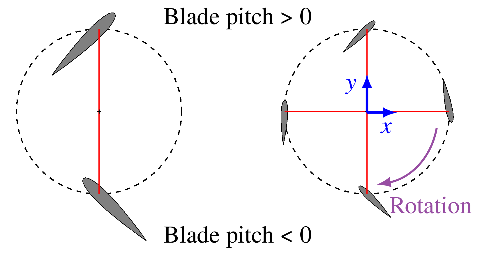
Cyclorotors present a compelling case for aerofoil optimisation, due to an inherent design trade-off linked to rotor solidity (), which represents the proportion of the rotor’s circumference that is occupied by blades. Rotor solidity is calculated using blade-count (), blade chord () and rotor radius () (Eq. 2). For a fixed blade pitch amplitude and RPM, there will generally be some minimum level of solidity required to reach a target level of thrust. The means by which this solidity is realised introduces competing aerodynamic consequences (Fig. 1). Configurations employing high blade counts with shorter chord lengths produce a consistent thrust output, but typically suffer from reduced efficiency.
| (2) |
This reduction in efficiency has been observed in both cyclorotors and VATs and is generally attributed to blade-to-blade interaction effects, arising from reduced inter-blade spacing, which promotes wake interaction between successive blades.(Benedict, 2010; Zhang et al., 2025). Cyclorotors additionally will often operate at high blade-pitch amplitudes to exploit the increased lift coefficient possible under dynamic stall. This operating mode promotes frequent LEV shedding and blade-vortex interactions. Given the strong dependence between aerofoil shape and flow separation, there is significant potential for aerofoil optimisation to improve the performance of high blade-count cyclorotors, thereby fully leveraging their inherent steady thrust characteristics. The concept of using cambered aerofoils in cyclorotors and optimising their shape has been explored in previous studies and have shown that the performance of a chosen cyclorotor configuration could indeed be improved through an optimisation of the aerofoil shape (Tang et al., 2017; Zhang et al., 2018). The range of different aerofoil shapes used in these studies remain relatively restrictive and do not encompass geometries with leading-edge droops, which have been associated with additional performance benefits (Ferrier, 2020).
Overall, devices that utilise blades operating in curvilinear flow are subject to multiple complex and overlapping effects. Classical aerodynamic theory typically relies on the assumption of rectilinear 2D flows, which constrains the accurate interpretation and modelling of the blade aerodynamics in these environments. Such frameworks do not account for the coupled effects of virtual camber, dynamic stall, and blade–wake interaction inherent to curvilinear flows. Consequently, the aerofoil geometry-driven control of LEV behaviour, and the effectiveness of optimisation across different solidity remain unresolved, resulting in the absence of a clear set of physics-based design principles for achieving an optimum aerofoil shape.
The aim of the current study is to investigate the governing physical mechanisms influencing aerofoil optimisation in a curvilinear flow. The study approaches this problem by optimising the aerofoil for a cyclorotor in the hover condition. The hover condition preserves the predominantly curvilinear inflow characteristics without the interference of the freestream effects, aligning with the primary focus of the investigation. Furthermore, in both maritime and aviation contexts, cyclorotors are frequently utilised in pure hover or at very low freestream speeds. To further examine the influence of rotor configuration on the resulting design principles, aerofoil optimisation is conducted for cyclorotors with 1-4 blades. This process will have the additional benefit of potentially highlighting how high blade-count cyclorotors can be made more viable to exploit their inherently steadier thrust output.
Although cyclorotors represent a specific manifestation of curvilinear blade motion, the optimisation outcomes are expected to retain relevance for other devices such as VATs. Despite serving distinct functional roles, both configurations experience comparable governing aerodynamic phenomena, including virtual camber, wake intersection, and dynamic stall. Consequently, while the exact optimal geometries may differ between applications, the underlying design principles are expected to remain broadly consistent.
2. Methodology
2.1. Cyclorotor configuration and parametrization
A 4-bladed cyclorotor operating at a representative Reynolds number of 30,000 was chosen as the primary baseline configuration for aerofoil optimisation (see Table 1 for details). In addition to the 4-blade configuration, blade-counts of 1-3 were also examined to assess the impact of blade-count on optimisation outcomes and to isolate the aerodynamic effects of aerofoil optimisation for both single-blade and multi-blade flow dynamics. A 4-bar linkage system is used to provide an approximately sinusoidal pitching profile between 45 (See supplementary material) (Cogan and Gagnon, 2022).
| Rotor Diameter () | 300 |
|---|---|
| Blade Chord () | 80 |
| Blade Span () | 200 |
| Number of Blades () | 1-4 |
| Max/Min Pitch | 45 |
| RPM Range | 24 |
| Reynolds Number | 30,000 |
| Default Aerofoil | NACA0015 |
For this baseline configuration, a NACA0015 profile was selected as the reference aerofoil due to its widespread adoption in prior cyclorotor investigations, facilitating direct comparison of aerodynamic performance (Benedict, 2010; Reed et al., 2019; Yu et al., 2016; Walther et al., 2019; Jarugumilli, 2013). Additional aerofoil geometries were generated through camberline modification of the baseline profile via the introduction of a leading-edge (LE) and trailing-edge (TE) droop to the camberline. Each droop is defined by a chordwise hinge-point location () and droop angle (), yielding four independent design variables governing the final aerofoil shape: , , and (Fig. 2). The subsequent camberline is defined by Eq. 3) (Huang, 2021; Huang and Gagnon, 2022; Woods et al., 2014). This definition allows independent control of the leading- and trailing-edge geometry expanding the accessible design space beyond conventional NACA profiles (Zhang et al., 2018). Droop angles are limited to , with hinge-point locations bounded by and .

| (3) |
The defined camberline was thickened with a 15% thickness NACA profile to generate the complete aerofoil geometry (Eq. 4). Using the slope () and position along the camberline, the surface coordinates were obtained from Eqns.4-5 (Abbott and Von Doenhoff, 1959).
| (4) |
| (5) |
To characterise the unsteadiness of the aerodynamics in this setup, the non-dimensional reduced frequency () is used, which is expressed as a function of the blade chord , flow velocity , and the blade pitching frequency . Flows with are generally classified as unsteady, while those with are considered highly unsteady (Leishman, 2006). For devices such as VATs and cyclorotors, the blade pitching frequency corresponds to the rotational frequency. The incident flow velocity experienced by the blades is primarily determined by the rotational speed of the cylindrical blade arrangement, (). As a result, the reduced frequency for these devices can often be expressed as , a term solely dependent on the rotor’s physical dimensions and independent of its pitching frequency or rotational speed. For the present configuration, the reduced frequency was found to be and thus would be classified as highly unsteady. While this exceeds values commonly observed in vertical-axis turbines () (Buchner et al., 2018; Rosado Hau et al., 2020), it accentuates the dynamic stall and vortex-dominated mechanisms central to this investigation.
From this baseline configuration and aerofoil parametrization, new designs were generated for the optimisation process to identify the best performing aerofoil.
2.2. Optimisation via Kriging
The optimisation in this study was conducted using a Kriging surrogate model, a technique that has been used successfully in multiple other optimisation studies involving unsteady flows (Tang et al., 2017; Choi et al., 2011; Raul and Leifsson, 2021). Unlike traditional regression or curve-fitting techniques, Kriging is a stochastic interpolation method that utilises a probabilistic framework to maximise the likelihood of the observed dataset. This foundation in probability allows for the uncertainty of the surrogate model to be estimated throughout the design space. This allows the use of the expected improvement () update criterion, which attempts to balance design improvement with design exploration, consequently alleviating the risk of the design optimisation converging on a local minima/maxima rather than the global minimum/maximum (Forrester et al., 2008).
An initial design space comprising of 20 aerofoil geometries was generated via a space-filling Latin hypercube. Subsequent update points were chosen with expected improvement criterion and the current global maximum of the surrogate model. Additional designs were iteratively added until no further improvement in the best evaluated design was observed after 6 consecutive updates. These methods were implemented in MATLAB using the toolbox from Forrester et al. (2008).
Aerofoil performance was quantified using the Figure of Merit () metric, which assesses efficiency in hover. This metric can be expressed in terms of Disk Loading () and Power Loading () through momentum theory given in equations 6, 7 and 8 (Benedict et al., 2015). It represents the ratio of the ideal power required for hover to the actual power consumed. For interim analysis the coefficients of force and torque were evaluated, which are defined in terms of the blade speed () due to rotation and the fluid density () (Eq. 9). For the single-bladed results thrust and power coefficients were normalised by the blade planform area (), as opposed to the full rotor projected area (rotor diameter blade span) typically employed in rotor-level performance assessment. For the four-bladed data, the full rotor projected area was used. The thrust direction is described with its angle () with respect to the vertical (Eq. 10).
The Kriging surrogate framework was subsequently used to identify candidate aerofoil geometries for computational evaluation, with optimisation targeting maximisation of .
| (6) |
| (7) |
| (8) |
| (9) |
| (10) |
2.3. Computational methodology


To evaluate the performance of different aerofoil shapes within the chosen design space, computational fluid dynamics (CFD) was used, facilitating a preliminary assessment without requiring the fabrication of a physical model for each updated aerofoil geometry. Two-dimensional unsteady Reynolds-averaged Navier Stokes equations (URANS) were solved using the commercial software Ansys FLUENT. This approach has been successfully applied to cyclorotor simulations in previous studies (Hu et al., 2016; Yun et al., 2007; Xisto et al., 2017; Zhang et al., 2018; Shi et al., 2022b; Yu et al., 2016; Hansen et al., 2021; Ullah et al., 2022).
The cyclorotor kinematics were simulated using separate meshes for the outer, rotating, and blade regions, that were then combined through overset meshing (Fig. 3). The rotating domain was set to a constant angular velocity, while the blade domains were pitched periodically using a custom user-defined function (UDF) to match the experimental cyclorotor’s kinematics. Each rotor revolution was resolved over 2000 timesteps. To ensure that the flow had reached a steadily periodic state, the simulations were run for 120 blade-passes, which was found to be sufficient for the 10-cycle averages to converge for cases using the baseline NACAS0015 aerofoil. The mean and phase-averaged forces/torques presented in this study were then taken over these last 10 revolutions.
To accurately model boundary layer separation and dynamic stall, no wall functions were used, and the mesh was refined to ensure . For the wider domain, the mesh was refined sufficiently to provide an average convective Courant number of . The SST turbulence model was selected for its proven suitability in flows experiencing dynamic stall, making it the most common choice for both vertical axis turbine (VAT) and cyclorotor simulations (Hansen et al., 2021; Hu et al., 2016; Zhang et al., 2018; Shi et al., 2022b; Yu et al., 2016; Ullah et al., 2022).
A single mesh was created for the blade-domain using the baseline NACA0015. By deforming this baseline mesh, the meshes for subsequent aerofoil designs could be created.
2.3.1. Blade mesh deformation


To simplify the creation of new meshes for different aerofoil shapes, the original mesh for the default NACA0015 was deformed to create the meshes for new aerofoils (Fig. 4). This approach has been used in prior studies and keeps the mesh topology constant, consequently reducing the noise associated with varying mesh topology (Toal, 2014; Huyse et al., 2002; Widhalm et al., 2007; Lassila and Rozza, 2010).
For the original NACA0015, a fixed set of positions on the camberline were used to generate a set of control points along the aerofoil’s surface (Eq. 5). A similar set of control points were then generated for the new aerofoil shape using the same set of positions on the camberline. This procedure yielded the required and displacement at each control point necessary to transform the baseline geometry into the updated aerofoil shape. Radial basis function interpolation was used to propagate the deformation in all areas of the surrounding domain (Forrester et al., 2008). Through this interpolation, the NACA0015 mesh could then be deformed to produce a new mesh. To constrain these deformations to primarily regions near the aerofoil, 20 additional control points were placed in the farfield at which zero deformation was defined.
2.4. Experiments


To validate the final results of the optimisation process, the baseline NACA0015 and the optimised aerofoil were tested experimentally. To aid explaining the results, the flowfields were determined with particle image velocimetry (PIV). The study was done in the University of Southampton’s recirculating water tunnel featuring a test section of . The tunnel was water-filled but operated without freestream flow to replicate hover conditions.
The experiments were conducted using a modular cyclorotor rig developed and constructed at the University of Southampton (Fig. 5). The rig is a modular design with 1-4 detachable arms and blades. The setup was suspended from an ATI Delta SI-660-60 force sensor placed such that its axis was inline with the rotation axis of the rotor. Forces were measured first in air to determine the inertial loads that were then subtracted from measurements in water to isolate the hydrodynamics forces. A sampling frequency of 1000Hz was used to acquire the data. To ensure that the blade aerodynamics has reached a statistically stationary condition, forces were recorded for 120 blade-passes. This was experimentally found to be sufficient for 10-cycle mean forces/torques to converge. From measurements with a stationary rotor and using Matlab, the signal noise was determined to be (). These frequencies were then filtered using a low-pass filter that was applied using forwards-backwards filtering, thus minimising the phase-change imparted by the filter on the data.
Along with the forces, flowfields were measured using particle image velocimetry (PIV). The flow was seeded with 55\unit[]\micro polyamide which were illuminated at the blade mid-span using overlapping LED light sources (ILA5150 GmbH LED V3 ()) from opposite sides of the rotor (Fig. 6(a)). Two Phantom V641 high-speed cameras (sensor size: 2560px 1600px) were mounted beneath the tunnel, viewing the illuminated plane through the tunnel’s glass floor. To further reduce the number of shadow regions for the 4-bladed configuration, a 2\unit[]\centi span section of the blades at the mid-span was replaced with clear acrylic. These sections were cut to the correct aerofoil shape via a waterjet cutter and then hand-polished (Fig. 6(b)).
Image pairs were acquired at a frequency of 100\unit with a time separation of . 260 frame-pairs were acquired continuously to capture a single revolution of the cyclorotor. The images were both acquired and processed to produce vector flowfields using LaVision’s DaVis software, employing a multi-pass method with a final window size of 32 px 32 px and 75% overlap. DaVis was further used to stitch the vector fields from each camera to provide an overall field-of-view of with a resolution of 1.6\unit\milli. The polynomial calibration necessary to achieve this was done using a square dotboard with 10\unit\milli separation inside the rotor where it was visible to both cameras.
To reduce the impact of erroneous vectors and small-scale turbulent features, the vector flow-fields were phase-averaged across 20 revolutions. The image acquisition was triggered at a common point within the cycle using a hall-effect sensor and a magnet attached to the rotor shaft. This ensured that all sets of 260 image pairs start from a common point within a cyclorotor’s operation and thus allowed the vectors to be averaged across all sets.


3. Results
3.1. Optimal aerofoil for the 4-bladed cyclorotor configuration
The surrogate model developed for aerofoil optimisation of the four-bladed cyclorotor enables visualisation of global performance trends across the design space (Fig. 7). Each tile within the figure represents a different combination of and , as shown by the major axis. Within each tile, Figure of Merit is mapped as a function of hinge-point locations and . The performance of the aerofoils exhibit strong sensitivity to the droop angles and , while demonstrating comparatively weak dependence on the position of the hinge points.
The optimal aerofoil geometry identified through the optimisation process exhibits a slight positive camber, with both the leading and trailing edges drooping by , thus reinforcing the virtual camber effect (Fig. 8). The performance gradients surrounding the peak region are relatively flat, with multiple neighbouring designs yielding similar results. The resulting optimised geometry agrees with the trends observed in previous studies on aerofoil camber in cyclorotors (Tang et al., 2017; Zhang et al., 2018).
These findings appear, at first glance, to contrast with results reported in studies examining asymmetric pitching profiles in cyclorotors, which demonstrated that introducing a positive bias to the pitching profile could improve performance by counteracting the virtual camber’s negative bias (Benedict, 2010; Shi et al., 2022a; Benedict et al., 2016; Walther et al., 2019). It was therefore expected that aerofoil optimisation could exhibit a similar trend. Instead, the optimised geometry appears to further augment the virtual camber effect.
Repeating the optimisation process for 1-3 blades resulted in very similar aerofoils, with the mean difference between surface points of . The small differences arise from the same low sensitivity in to small variations in aerofoil shape observed near the optimum for the 4-bladed configuration (Fig. 7). To reduce experimental costs, the following experimental results in this study have used the aerofoil optimised for the 4-bladed configuration.
3.2. LEV-dynamics of a single blade in curvilinear flow
To illustrate the principal flow features, PIV data for a single-bladed cyclorotor employing the baseline NACA 0015 aerofoil are presented, showing the mean velocity field alongside instantaneous vorticity distributions around the blade at two representative azimuthal positions (Fig. 9). The azimuthal positions are presented in Fig. 10. As the blade goes through its maximum (A) and minimum (B) pitch they undergo dynamic stall and shed large LEVs (Fig. 9). The blade kinematics induces a mean throughflow where the flow is ingested into the rotor’s upper-half, passes around the right-hand side of the rotor and is then ejected out of the bottom across a wide arc. The flow is accelerated both upon entering and exiting the rotor. As the blade re-enters the upper-half of the rotor (), its motion opposes the induced throughflow and generates a recirculatory flow region (C). The LEV created during negative pitch (B) will detach and remain in this region as it breaks down and dissipates. In contrast, the LEV generated during positive pitch, typically detaches around () and is convected rightwards, away from the rotor, by the induced mean flow.
The force and torque profiles on a single bladed cyclorotor can be divided into four quadrants (Q1-Q4) (Fig. 10). The instantaneous resultant thrust () does not maintain a constant direction over a cycle, necessitating a component-wise analysis of and force contributions.


The force/torque components for the baseline NACA0015 all exhibit a primary peak in Q1, corresponding to the minimum blade pitch (-), and a smaller secondary peak in Q3, corresponding to the maximum blade pitch (+). The asymmetry in the peaks can be attributed to the virtual camber effect which introduces a negative offset to the effective angle-of-attack (Fig. 11). This offset increases thrust production under negative blade pitch conditions (Q1) while reducing thrust generation under positive blade pitch (Q3). In Q2 and Q4, the blade pitch returns to zero, resulting in comparatively lower aerodynamic loading in these regions.


The and components remain positive over the majority of the rotational cycle, with both primary and secondary peaks being positive. In contrast, the peaks of have opposing signs, causing them to largely cancel out when averaged over a full revolution. This results in a relatively small mean value for compared to , despite their similar instantaneous magnitudes. The greater magnitude of the primary peak due to virtual camber makes the mean value positive, causing the mean resultant force vector to rotate clockwise from the vertical ().
When using the optimised aerofoil for the 4-bladed configuration (Fig. 8), the primary differences seen are a 16% increase in during the primary peak (Q1) and a 33% increase in during the secondary peak (Q3). Otherwise however, the same general trends of the forces and torques remain consistent with those observed for the baseline NACA0015.
To explain these observations, the vorticity fields derived from PIV data are examined. For both aerofoil types, LEVs are shed as the blades undergo dynamic stall at minimum pitch (Fig. 12-12) and maximum pitch (Fig. 12-12). Due to the negative effective angle-of-attack offset induced by virtual camber, the absolute magnitude of angle-of-attack is greater during the negative pitch phase. Consequently, a more prominent negative LEV is observed at minimum pitch (Fig. 12-12). For the optimised aerofoil, the negative LEV is much smaller and more closely attached to the surface of the blade (Fig. 12). Conversely the positive LEV during positive pitch shows greater separation from the blade surface (Fig. 12). Since flow separation is typically accompanied by a loss in lift and increase in drag, these differences in the LEVs align with what was observed for the single blade forces, which showed the optimised aerofoil improving thrust production in Q1 but increasing torque in Q3 (Fig 10).
3.3. Impact of blade-count upon LEV characteristics

Differences in the LEV shedding characteristics are observed with increasing blade count from 1 to 4 despite the blade kinematics remaining constant. In the single-bladed baseline case, the negative LEV is characterised by its larger size and pronounced separation (Fig. 12). In the 4-bladed configuration with the same baseline aerofoil however, the same LEV appears to be much smaller and less distinct (Fig. 13). While the LEV does eventually detach, separation occurs much later in the cycle and after the primary thrust peak has ended (Fig. 13). The relative differences between the baseline and optimised aerofoil for the 4-bladed configuration do however remain similar to what was seen for the 1-bladed configuration. With the optimised aerofoil, the negative LEV is further reduced in size and its separation is suppressed (Fig. 13,13).
This change in the LEV characteristics with different blade-counts can be explained through an examination of the mean flowfields (Fig. 14). For both blade-counts of 1 and 4, the overall structure of the mean flow remains consistent: flow is ingested through the top, passed around the right-hand side of rotor and then ejected out of the bottom in a wide arc. The primary distinction lies in the magnitude of this throughflow, with the maximum mean throughflow speed () increasing by in the four-bladed configuration relative to the single-bladed case).

The magnitude of the throughflow in a cyclorotor is approximately proportional to its thrust (),
| (11) |
and for a fixed pitching profile the thrust is proportional to both the blade-count () and the blade speed (),
| (12) |
Consequently when comparing two cyclorotors with different blade-counts for either a fixed RPM or fixed thrust (and therefore throughflow):
| (13) |
This ratio is important, since the throughflow suppresses the angle-of-attack of the blades in the lower half of the rotor where the majority of the thrust is produced. The extent to which the angle-of-attack is suppressed is then a function of the ratio of throughflow to blade-speed (Fig. 15) and can be mathematically represented by:
| (14) |
Consequently, the effective angle-of-attack of blades in a cyclorotor with a higher blade-count is significantly more suppressed, which explains the differences seen in the negative LEV when comparing the 1- and 4-bladed results (Figs. 12-13). With a larger effective angle-of-attack, the blade in the 1-bladed configuration undergoes a much deeper dynamic stall, as characterised by the large LEV that is shed (McCroskey, 1981). Conversely, the blades in the 4-bladed configuration undergo a much lighter dynamic stall with a lower degree of flow separation.

3.4. Influence of LEV separation upon cyclorotor efficiency

The connection between blade-count and the extremity of dynamic stall has an impact upon aerofoil optimisation. Using the aerofoil optimised for the 4-bladed configuration, Figure of Merit was measured experimentally for 1-4 blades across a range of RPM (Fig. 16). For the 4-bladed configuration that the aerofoil was optimised for, a notable improvement can be seen when using the optimised aerofoil (14% at 24 RPM). For all blade-counts lower than 4, however, there is a negligible difference to performance when using the optimised aerofoil. CFD showed that using the true optimised aerofoil for each blade-count did not improve either, due to the low sensitivity to aerofoil geometry around the optimum (Section 3.1).
The observed trends are attributable to differences in extremity of the dynamic stall noted during the primary thrust peak when using different blade-counts (Sec. 3.3). For the rotor geometry used in this particular study, the dynamic stall for blade-counts less than 4 is likely too deep for any change in aerofoil shape to prevent the LEV from separating. This can be seen in the single-bladed results, where the LEV during the primary thrust peak is very large and distinct (Fig. 12). For 4 blades however, the dynamic stall was much lighter with a LEV that separates much later (Fig. 13). This consequently allows an adjustment in aerofoil shape to suppress the LEV. Given the lift degradation and drag augmentation associated with separated flow, this distinction explains why measurable performance improvements emerge in the 4-bladed configuration but remain absent in the lower blade-counts. A similar observation has been made for VATs where vortex generators were used to improve performance by preventing flow separation (De Tavernier et al., 2021).
4. Conclusion
The present study investigated the key physical mechanisms influencing the optimisation of foils in curvilinear flow. URANS simulations in conjunction with a Kriging model were used to optimise the aerofoil of a 4-bladed cyclorotor. The results were then validated with a physical experiment measuring both the forces and the flowfields.
Aerofoil geometry optimisation was shown to improve cyclorotor performance. For the four-bladed configuration, the optimal aerofoil—characterised by approximately leading- and trailing-edge droop—suppressed separation of the leading-edge vortex formed during the primary thrust peak. Mitigation of separation-associated lift loss and drag augmentation enabled a 14% increase in Figure of Merit.
This performance enhancement is subject to a governing constraint: optimisation effectiveness depends strongly on dynamic stall severity, which is regulated by rotor solidity. Under deep dynamic stall conditions, leading-edge vortex separation remains dominant and cannot be suppressed through aerofoil shape modification alone. Effective optimisation therefore requires a flow regime in which the vortex remains predominantly attached prior to geometric intervention.
For cyclorotors operating in hover, this dependency renders optimisation ineffective at low solidity. Higher-solidity configurations induce stronger throughflow, reducing effective blade incidence during the primary thrust phase and promoting the lighter dynamic stall conditions necessary for vortex attachment and optimisation viability.
Overall, aerofoil optimisation in cyclorotors cannot be conducted in isolation. Rotor solidity, reduced frequency, and blade kinematics collectively govern dynamic stall behaviour and must be considered concurrently with aerofoil geometry in defining optimal rotor design.
References
- Theory of Wing Sections - Including a Summary of Airfoil Data. Dover edition, General Publishing Company Ltd., Toronto. Cited by: §2.1.
- Effects of asymmetric blade-pitching kinematics on forward-flight performance of a micro-air-vehicle-scale cycloidal-rotor. Journal of Aircraft 53 (5), pp. 1567–1572. External Links: Document, ISSN 15333868 Cited by: §3.1.
- Experimental Investigation of Micro Air Vehicle Scale Helicopter Rotor in Hover. International Journal of Micro Air Vehicles 7. External Links: Document Cited by: §2.2.
- Fundamental understanding of the cycloidal-rotor concept for micro air vehicle applications. Ph.D. Thesis, University of Maryland. Cited by: §1, §2.1, §3.1.
- Dynamic stall in vertical axis wind turbines: Scaling and topological considerations. Journal of Fluid Mechanics 841, pp. 746–766. External Links: Document, ISSN 14697645 Cited by: §2.1.
- Enhancement of a flapping wing using path and dynamic topology optimization. AIAA Journal 49 (12), pp. 2616–2626. External Links: Document, ISSN 00011452 Cited by: §2.2.
- Numerical Analysis of cyclorotor aerodynamic properties in hovering state. IOP Conference Series: Materials Science and Engineering 1226 (1), pp. . External Links: Document Cited by: §2.1.
- Controlling dynamic stall using vortex generators on a wind turbine airfoil. Renewable Energy 172, pp. 1194–1211. External Links: Document, ISSN 18790682 Cited by: §3.4.
- Investigation on the aerodynamic performance of cycloidal rotors with active leading-edge morphing. Ph.D. Thesis, University of Glasgow. Cited by: §1.
- Engineering design via surrogate modelling : a practical guide. Wiley ; John Wiley [distributor]. External Links: ISBN 9780470060681 Cited by: §2.2, §2.2, §2.3.1.
- Numerical modelling and optimization of vertical axis wind turbine pairs: A scale up approach. Renewable Energy 171, pp. 1371–1381. External Links: Document, ISSN 18790682 Cited by: §1, §2.3, §2.3.
- Investigation of unsteady aerodynamics effects in cycloidal rotor using RANS solver. Aeronautical Journal 120 (1228), pp. 956–970. External Links: Document, ISSN 00019240 Cited by: §2.3, §2.3.
- Relying on Dynamically Morphing Blades to Increase the Efficiency of a Cycloidal Rotor. IOP Conference Series: Materials Science and Engineering 1226 (1), pp. 012014. External Links: Document, ISSN 1757-8981 Cited by: §2.1.
- Evaluate the Performance of a Camber Controlled Cycloidal Rotor. Master’s Thesis, University of Stuttgart. Cited by: §2.1.
- Probabilistic approach to free-form airfoil shape optimization under uncertainty. AIAA Journal 40 (9), pp. 1764–1772. External Links: Document, ISSN 00011452 Cited by: §2.3.1.
- An Experimental Investigation of a Micro Air Vehicle-Scale Cycloidal Rotor in Forward Flight. Ph.D. Thesis, University of Maryland. Cited by: §2.1.
- Parametric free-form shape design with PDE models and reduced basis method. Computer Methods in Applied Mechanics and Engineering 199 (), pp. . External Links: Document, ISSN 00457825 Cited by: §2.3.1.
- Principles of helicopter aerodynamics. 2 edition, Cambridge University Press. Cited by: §2.1.
- The Phenomenon of Dynamic Stall. Technical report NASA. Cited by: §3.3.
- Flow curvature effects on Darrieus turbine blade aerodynamics. Journal of energy 4 (2), pp. 49–55. External Links: Document, ISSN 01460412 Cited by: §1.
- The onset of dynamic stall revisited. Experiments in Fluids 52 (3), pp. 779–793. External Links: Document, ISSN 07234864 Cited by: §1.
- Surrogate-based aerodynamic shape optimization for delaying airfoil dynamic stall using Kriging regression and infill criteria. Aerospace Science and Technology 111. External Links: Document, ISSN 12709638 Cited by: §2.2.
- Force and Flowfield measurements to understand unsteady aerodynamics of cycloidal rotors in hover at ultra-low Reynolds Numbers. International Journal of Micro Air Vehicles 11, pp. . External Links: Document Cited by: §2.1.
- A critical analysis of the stall onset in vertical axis wind turbines. Journal of Wind Engineering and Industrial Aerodynamics 204. External Links: Document, ISSN 01676105 Cited by: §2.1.
- Analysis of flow-induced performance change of cycloidal rotors: Influence of pitching kinematic and chord-to-radius ratio. Ocean Engineering 263. External Links: Document, ISSN 00298018 Cited by: §3.1.
- Numerical investigations on unsteady vortical flows and separation-induced transition over a cycloidal rotor at low Reynolds number. Energy Conversion and Management 266. External Links: Document, ISSN 01968904 Cited by: §2.3, §2.3.
- Development of a meso-scale cycloidal-rotor aircraft for Micro Air Vehicle Application. International Journal of Micro Air Vehicles 9 (3), pp. 218–231. External Links: Document Cited by: §1.
- Unsteady aerodynamic optimization of airfoil for cycloidal propellers based on surrogate model. Journal of Aircraft 54 (4), pp. 1241–1256. External Links: Document, ISSN 15333868 Cited by: §1, §2.2, §3.1.
- On the Potential of a Multi-Fidelity G-Pod Based Approach for Optimization and Uncertainty Quantification. In ASME Turbo Expo 2014: Turbine Technical Conference and Exposition, External Links: Link Cited by: §2.3.1.
- Two-Dimensional URANS Numerical Investigation of Critical Parameters on a Pitch Oscillating VAWT Airfoil under Dynamic Stall. Energies 15 (15). External Links: Document, ISSN 19961073 Cited by: §2.3, §2.3.
- Voith Schneider Propeller (VSP). External Links: Link Cited by: §1.
- Symmetric versus asymmetric pitching of a cycloidal rotor blade at ultra-low Reynolds numbers. Journal of Aircraft 56 (3), pp. 1179–11199. External Links: Document, ISSN 15333868 Cited by: §2.1, §3.1.
- Comparison between Gradient-free and Adjoint Based Aerodynamic Optimization of a Flying Wing Transport Aircraft in the Preliminary Design. In 25th AIAA Applied Aerodynamics Conference, Miami. Cited by: §2.3.1.
- Aerodynamic Modelling of the Fish Bone Active Camber Morphing Concept. In RAeS Applied Aerodynamics Conference, Swansea University. Cited by: §2.1.
- Parametric Analysis of a Large-Scale Cycloidal Rotor in Hovering Conditions. Journal of Aerospace Engineering 30 (1). External Links: Document, ISSN 0893-1321 Cited by: §2.3.
- Two-dimensional and three-dimensional numerical simulations of cycloidal propellers in hover. Proceedings of the Institution of Mechanical Engineers, Part G: Journal of Aerospace Engineering 232 (7), pp. 1223–1234. External Links: Document Cited by: §2.1, §2.3, §2.3.
- Design of a New Unmanned Aerial Vehicle Cyclocopter. Journal of the American Helicopter Society 52, pp. 24–35. External Links: Document Cited by: §2.3.
- The effect of aerofoil camber on cycloidal propellers. Aircraft Engineering and Aerospace Technology 90 (8), pp. 1156–1167. External Links: Document, ISSN 17488842 Cited by: §1, §2.1, §2.3, §2.3, §3.1.
- Effect of blade-to-blade wake interference on aerodynamic performance of darrieus vertical axis wind turbines. Energy 337. External Links: Document, ISSN 18736785 Cited by: §1.