Learning Thermal-Aware Locomotion Policies for an Electrically-Actuated Quadruped Robot
Abstract
Electrically-actuated quadrupedal robots possess high mobility on complex terrains, but their motors tend to accumulate heat under high-torque cyclic loads, potentially triggering overheat protection and limiting long-duration tasks. This work proposes a thermal-aware control method that incorporates motor temperatures into reinforcement learning locomotion policies and introduces thermal-constraint rewards to prevent temperature exceedance. Real-world experiments on the Unitree A1 demonstrate that, under a fixed 3 kg payload, the baseline policy triggers overheat protection and stops within approximately 7 minutes, whereas the proposed method can operate continuously for over 27 minutes without thermal interruptions while maintaining comparable command-tracking performance, thereby enhancing sustainable operational capability.
I Introduction
Quadrupedal robots exhibit strong terrain adaptability in scenarios such as inspection, transport, and disaster response, making them ideal candidates for continuous-operation tasks [1, 2]. However, their motors typically operate under cyclic high-torque loads, and factors such as load variations, elevated ambient temperatures, and limited cooling can cause motor heating to deviate significantly from design assumptions. Although nominal payloads and endurance specifications are usually provided during the robot design phase, these metrics are often based on ideal cooling conditions and moderate levels of locomotion. In real-world tasks, motor temperatures can quickly accumulate and trigger overheat protection, leading to performance degradation or task interruption. This issue becomes particularly pronounced under long-duration tasks, high payloads, or harsh outdoor conditions, posing a key limitation to the sustainable locomotion of quadrupedal robots.
Existing approaches for addressing motor thermal limitations can be broadly divided into hardware-level thermal capability enhancement and control-layer thermal constraint handling. The former aims to increase a motor’s allowable thermal envelope—e.g., by improving heat dissipation or increasing thermal mass/capacity—to delay the onset of overheating and sustain higher torque output [3, 4, 5]. However, such approaches do not exploit the intrinsic coupling between thermal dynamics and power delivery, and thus cannot proactively determine thermal violations under specific task loads or environmental conditions. As a result, protective control strategies remain necessary to guarantee continuous operation. In contrast, control-layer approaches incorporate thermal models or temperature feedback into cost functions or safety constraints, enabling policies or controllers to actively satisfy thermal safety requirements during execution [6]. These studies mainly target fixed-base systems, such as robotic arms, where thermal constraints typically apply to static or slowly varying trajectories and can be enforced simply by limiting torque or power. In quadrupedal robots, however, torque and power output not only influence motor temperature but are also critical for maintaining dynamic balance, foot-ground contact, and task execution. Consequently, thermal management and stability control are tightly coupled, and there is currently a lack of effective methods for proactively preventing motor overheating in legged robots.
To the end, this work proposes a thermal-aware locomotion control method for quadrupedal robots. The method incorporates motor temperatures and their dynamic evolution into the state space of a reinforcement learning policy and designs thermal-constraint rewards to encourage the policy to adapt its behavior when approaching thermal limits, thereby delaying the activation of overheat protection. The approach does not rely on additional hardware cooling and can accommodate sustainable operation under varying task and thermal conditions. We validate the proposed method in both simulation and on the real Unitree A1 platform. Results show that the method significantly reduces motor overheating risk while maintaining comparable command-tracking performance and extends continuous operation under fixed-load tasks from approximately 7 minutes to over 27 minutes without thermal interruptions, demonstrating the potential of proactive thermal management to enhance the endurance of quadrupedal robots.
II Motor Thermal Model for Quadruped Robots
II-A Single-Motor Thermal Model
The temperature of a single motor can be effectively predicated by a first-order thermal model [7]. The temperature evolution of the motor is mainly attributed to the Joule heating induced by the winding current and the thermal interaction with the ambient environment. According to [8], the thermal behavior of the motor can be described by a single time constant thermal equation, representing the thermodynamic behavior of a homogeneous body at rest heated by electric current:
| (1) |
where is the motor temperature, is the ambient temperature, and are the equivalent thermal capacitance and thermal resistance between the motor and the environment, and is the equivalent electrical resistance of the motor windings.

II-B Whole-body Thermal Model of the Quadruped Robot
Due to the compact structure of quadruped robots, joint motors are densely distributed in space, resulting in significant thermal coupling effects between motors. Therefore, modeling each motor independently as a first-order thermal system is difficult to accurately predicate the temperature of all motors in the quadruped robot during locomotion. According to [9], we construct a whole-body thermal model of the quadruped robot, as shown in Fig. 2.

represents the -th motor corresponding to the single-motor thermal model shown in Fig. 1, serving as a thermal node. represents the thermal node associated with the onboard computer. represents the equivalent thermal resistance between node and node . The heat transferred between neighboring nodes can be written as:
| (2) |
For any thermal node , considering its thermal interactions with neighboring nodes, its temperature can be modeled as:
| (3) |
where is the set of all neighboring nodes thermally connected to node , and is additional heat generated by joint friction and the constant heat from the motor driver. Detailed modeling procedures can be found in [9].
The whole-body thermal model of the quadruped robot can be formulated in state-space form, and the continuous-time system is further discretized as follows:
| (4) |
where is the temperatures of all nodes including motors, computer, and environment, and is the generated heat at each node, defined as . is the system matrix describing the thermal coupling between nodes, and is the input matrix, is the sampling interval, and is the sampling index.
III Thermal-Aware Locomotion Policy Design
III-A Training Framework
According to prior reinforcement learning studies on quadrupedal locomotion control [10, 11], we establish a policy training framework for motor heat management, as illustrated in Fig. 3. The Actor outputs an action based on the robot’s state and its task which is added to the nominal joint angles to determine the target joint positions. Then target positions are fed into joint PD controllers to generate either the joint torques in the simulation or the motor currents for the real robot, thereby achieving quadrupedal locomotion. During training, the optimization process consists of two stages: Hybrid Internal Optimization (HIO), which updates the encoder network, and Proximal Policy Optimization (PPO) [12], which optimizes the Actor and Critic network.

In real-world applications, it is difficult to access certain state information including linear velocity, and measurements obtained from the IMU and motor encoders are corrupted by noise. Therefore, quadrupedal locomotion is naturally formulated as a Partially Observable Markov Decision Process (POMDP). To improve value estimation during training and ensure policy convergence, we adopt an asymmetric Actor–Critic framework. In the simulation training phase, the Critic receives additional privileged observations including linear velocity and external force , in addition to the proprioceptive observation . The specific expression is as follows:
| (5) | ||||
where denotes the commanded velocity in the robot’s base frame. and denote the angular velocity and gravity vector in the robot’s base frame. , and denote the motor positions, velocities and temperatures. denotes the previous action.
In addition to the proprioceptive observation , the observation for the Actor also includes the estimated velocity and the latent feature vector with the encoder using the previous six frames of proprioceptive observations to generate them. Detailed implementation can be found in [11].
III-B Temperature Randomization
We incorporate the whole-body thermal model of the quadruped robot into the simulation to update motor temperatures of all agents in real time. Since torque is approximately linearly proportional to current , we use the motor torque as a substitute for the motor current . Meanwhile, the torque varies at a much higher frequency than the update rate of the thermal model, we therefore use the root-mean-square (RMS) of the torque derived from Joule heating theory as the effective thermal input to ensure modeling accuracy:
| (6) |
where denotes the -th torque sample within the thermal model update interval. The thermal model parameters for the Unitree A1 are taken from [9], and the thermal model is updated at the same frequency as the Actor outputs.
To reduce the sim-to-real gap, we apply domain randomization during training using the parameters listed in Table. I to initialize the robot states. Taking the limited episode length of each agent into consideration, we initialize motor temperature within the range , ensuring a greater number of samples near at the beginning to improve the efficiency of policy learning. Furthermore, under conditions without payload or persistent external forces, motor temperatures rarely reach the overheat threshold. To construct operating conditions with realistic motor overheat risk, we additionally introduce domain randomization of eccentric payloads and persistent external forces.
| Parameters | Range [Min, Max] |
|---|---|
| Payload Mass | |
| CoM Displacement | |
| External Force | |
| Ground Friction | |
| Initial Joint Positions | |
| System Delay | |
| Motor Strength | |
| Initial Motor Temperature | |
| Environment Temperature |
III-C Reward Function
To guide the Actor in learning a locomotion policy with motor heat management, we design a reward function related to motor temperature that encourages the robot to reduce heat generation of overheated motors. Due to the strong inertia of the whole-body thermal model, motor temperatures cannot decrease significantly within an episode. Following [13], we convert the inequality constraint requiring the motor temperature to remain below into a Control Barrier Function (CBF) [14], which improves the responsiveness of the reward to actions outputted by the Actor:
| (7) |
The CBF condition effectively imposes a constraint on the motor temperature derivative: when the temperature approaches or exceeds the threshold, the system is required to satisfy to prevent further heating. However, within an episode, typically exhibits limited variation, meaning that the reward can still be heavily influenced by the initial temperature. To mitigate this initialization bias and make the reward more focused on the motors whose temperature is near the threshold, we introduce a clipped temperature and compute penalties only based on violations of the CBF constraints for each motor. All rewards and their weights are summarized in Table II.
| Reward Item | Equation | Weight |
|---|---|---|
| Linear velocity tracking | 1.0 | |
| Angular velocity tracking | 0.8 | |
| Linear velocity (z) | -2.0 | |
| Angular velocity (roll-pitch) | -0.05 | |
| Orientation | -0.2 | |
| Joint accelerations | -2.5e-7 | |
| Termination | / | -200 |
| Body height | -1.0 | |
| Foot clearance | -0.01 | |
| Action rate | -0.01 | |
| Smoothness | -0.01 | |
| Motor temperature | 2.0 |
To ensure that the CBF constraint remains satisfied even when a high-temperature motor receives zero input, we determine the weight coefficient based on (4):
| (8) |
where denotes a temperature vector in which all nodes except the environmental node are set to . All parameters of rewards are reported in Table III.
| Motor Temperature Reward Function | Other Reward Function | ||
|---|---|---|---|
| 0.25 | |||
| 0.3 m | |||
| 0.35 | -0.2 m | ||
IV EXPERIMENTS AND RESULTS
IV-A Experimental Setup
We used the Isaac Gym simulator to build the simulation environment for training, and deployed 8192 robot agents in parallel to concurrently learn for 6000 epochs with the episode length of each agent set to 100 time steps(20 s). Given our focus on the management of motor temperature during quadrupedal locomotion, we trained the policies to walk omnidirectionally on flat ground. To enhance policy stability and robustness, We applied uniform random noise ranging from -2 cm to +2 cm to the terrain, which included light slopes up to a 2% incline [15]. For sim-to-sim validation, we used Gazebo as the simulation environment, which allows direct and real-time access to accurate measurements such as velocity, GRFs(ground reaction forces), and base height for detailed experimental analysis. In real-world experiments, the trained encoder network shown in Fig. 3 was used to estimate the base velocity, and temperatures feedback from motors were directly fed into the policy as inputs.
IV-B Real-world Locomotion Results
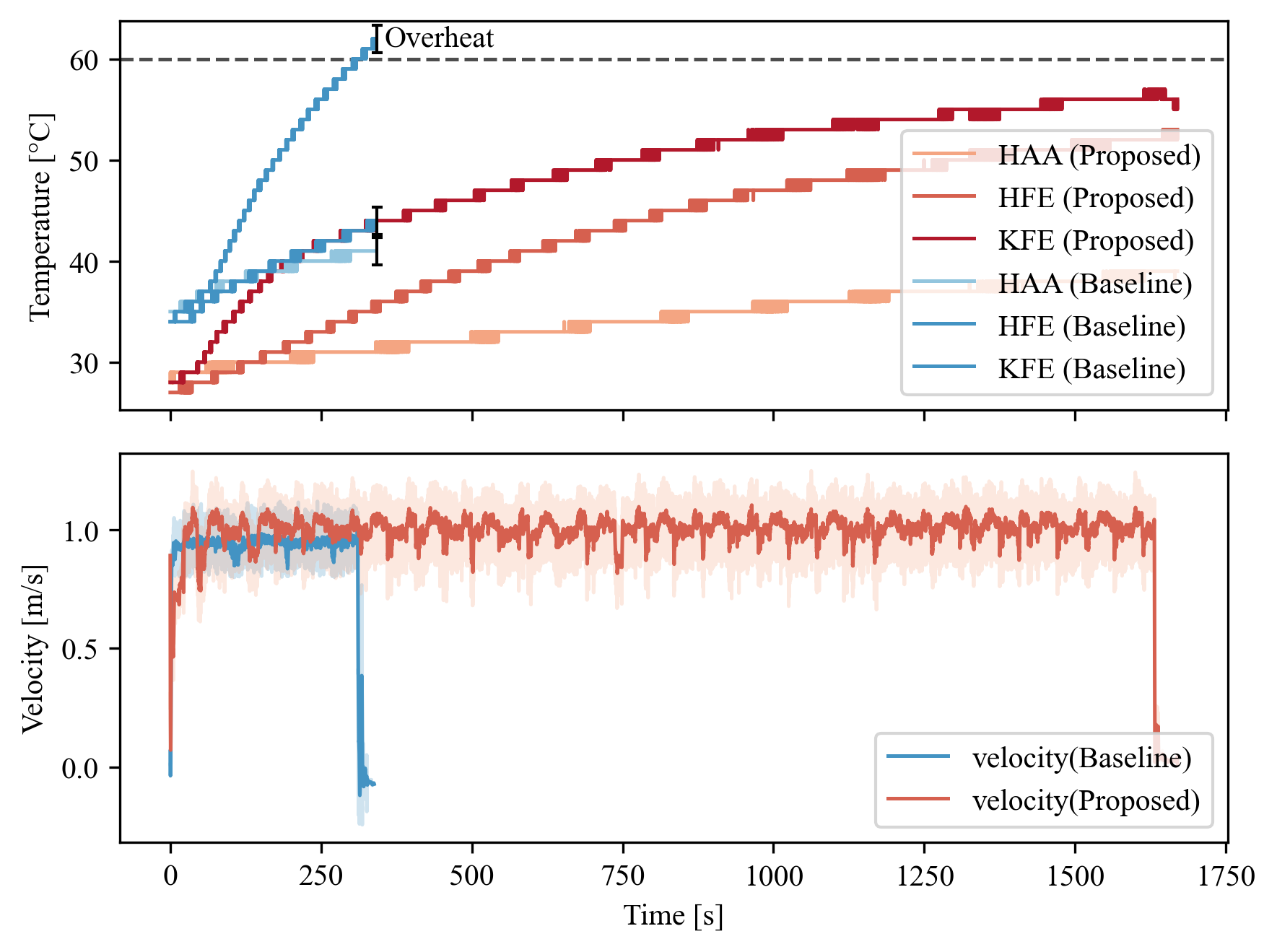
To validate the effectiveness of our policy, we used a policy trained without the motor temperature reward as the baseline, and compared the motor temperature evolution under different strategies. In real-world experiments, a 3 kg external payload was mounted on the robot’s back to increase the risk of motor overheating. The robot was commanded to move forward at 1 m/s and walk continuously on flat terrain, as shown in Fig. 4. The curves in Fig. 5 show that the baseline failed to continue walking in only 7 minutes due to overheating of the front-left knee motor. In contrast, controlled by the proposed policy, the robot walked stably under the same conditions until the battery was depleted. During more than 26 minutes of continuous locomotion, the temperatures of all motors remained below the threshold temperature .

IV-C Analysis of Thermal-Aware Locomotion Performance
The hardware experiments demonstrate that the proposed thermal-aware policy substantially mitigated motor temperature rise under load while preserving tracking performance. This section examines the underlying mechanism enabling this behavior.
Mechanism analysis requires access to joint torques, three-dimensional ground reaction forces, joint-to-foot Jacobians, and body posture. Since accurate 3-D force measurements are difficult to obtain on hardware, the analysis was conducted in simulation. To accentuate the differences between controllers, a more challenging condition was considered by applying an additional 4 kg lateral load to the upper-left region of the torso while commanding forward locomotion at . This configuration increased the coupling between posture regulation and load distribution and facilitates observation of the resulting compensatory behaviors.
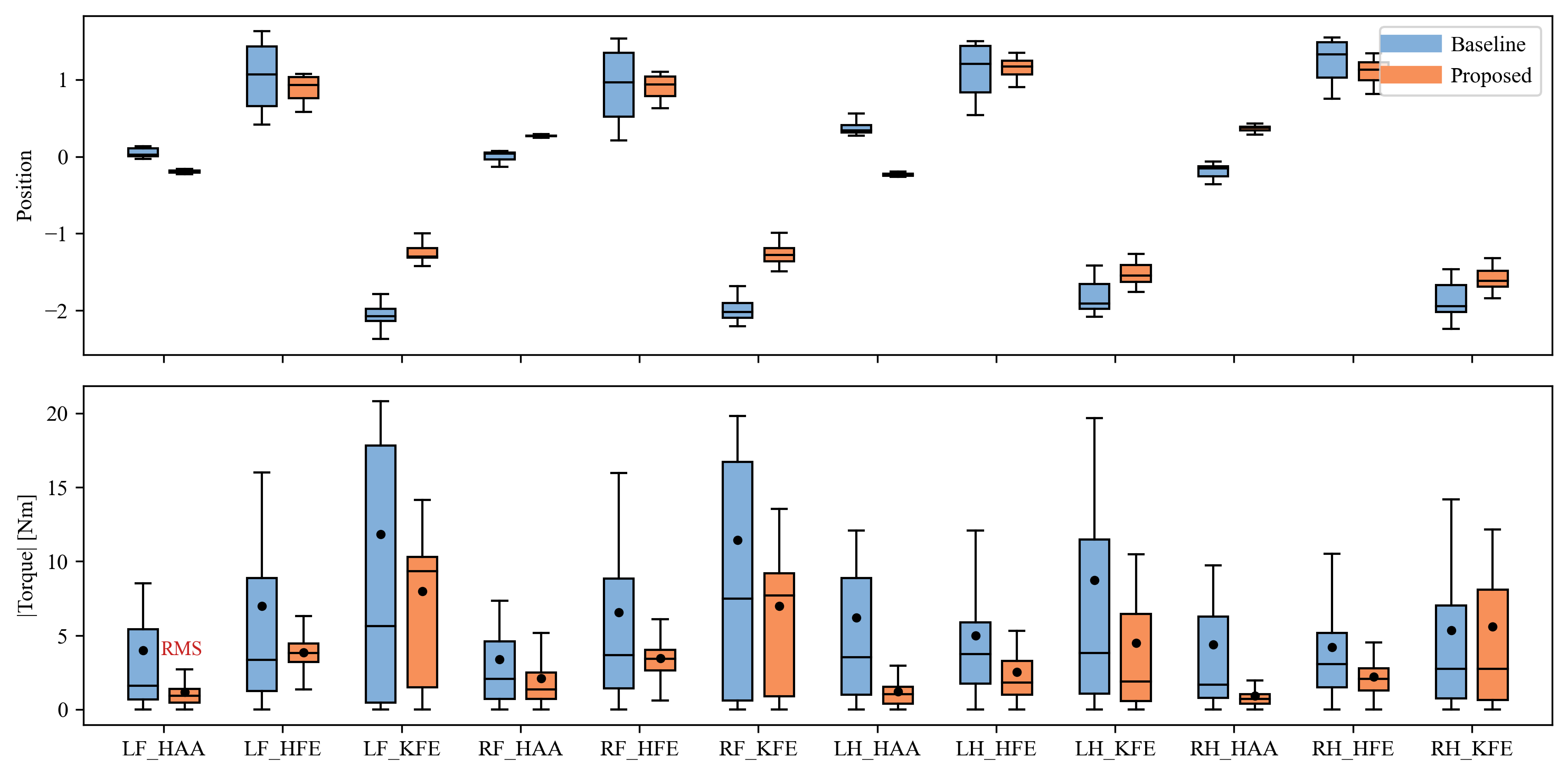
Fig.6 reports joint-space statistics. Under the proposed controller, joint angle excursions were reduced, and both peak and RMS joint torques were substantially lower relative to the baseline. As motor heating is closely related to torque magnitude and duration, these reductions are consistent with the observed thermal behavior. However, torque reduction alone does not establish whether support capability is altered.
To assess support characteristics, ground reaction forces were examined shown in Fig.7. Although the proposed controller exhibited a higher stepping frequency, peak vertical forces and time-averaged vertical impulse remained comparable to the baseline, while horizontal components remained relatively small. This indicates that vertical support was preserved despite reduced torque expenditure, consistent with the tracking performance observed on hardware.

Given that support characteristics are maintained while torque demand is reduced, the geometric mapping between joint torques and contact forces is considered. Fig.8 shows that steady-state locomotion under the proposed controller features a greater pitch angle and a higher center of mass, implying a modified torque-to-force transmission geometry.

This interpretation is quantitatively supported by the joint-to-foot Jacobian analysis in Fig.9. The absolute Jacobian difference is computed at three representative phases of stance. Positive values indicate that the same joint torque produces greater force in the associated direction. The vertical () components were consistently positive, whereas horizontal components were slightly reduced. Combined with the dominance of vertical support forces during trotting locomotion , this indicates enhanced vertical force transmission efficiency.

These results collectively demonstrate that the proposed controller leveraged locomotion redundancy through posture adaptation, improved vertical transmission efficiency, and reduced torque requirements for equivalent support. This mechanism explains the reduced thermal load without degradation of tracking performance.
V CONCLUSION
In this work, we propose a novel approach for motor thermal management during quadrupedal robot locomotion. We first establish a full-body thermal model of the quadruped robot and integrate it into the Isaac Gym simulation environment to enable real-time estimation of motor temperatures. Based on a relaxed control barrier function, we then design a reward function that penalizes motor overheating, and use reinforcement learning to train a thermal-aware locomotion policy. Finally, the proposed policy is deployed on a real robot and evaluated in comparison with a baseline method. Under a 3 kg payload, the robot walks continuously and stably for extended periods while keeping all motor temperatures below the threshold. Furthermore, we conduct a comparative analysis of the robot’s motion states and mechanical characteristics under ours policy and the baseline to provide insights into the underlying mechanism through which our approach achieves motor heat management.
Despite these promising results, there remains substantial room for improvement and future research. The current policy tends to adopt conservative walking postures even when motor temperatures are low, which limits the robot’s mobility and hinders performance on challenging terrains such as steep slopes or stairs. In future work, we plan to incorporate multi-mode recognition, enabling the robot to adapt its behavior based on motor temperature: maximizing locomotion performance under low-temperature conditions while prioritizing motor thermal safety under high-temperature conditions, thereby achieving a balance between performance and safety.
ACKNOWLEDGMENT
Acknowledgements This work was partially supported by the National Natural Science Foundation of China (No. 52375014), Guangdong Innovative and Entrepreneurial Research Team Program (No. 2019ZT08Z780), and Dongguan Introduction Program of Leading Innovative and Entrepreneurial Talents (No. 20181220).
References
- [1] Omer Kemal Adak and Kemalettin Erbatur, ”Bound Gait Reference Generation of a Quadruped Robot via Contact Force Planning,” International Journal of Mechanical Engineering and Robotics Research, Vol. 11, No. 3, pp. 129-137, March 2022. DOI: 10.18178/ijmerr.11.3.129-137
- [2] Khalid Hussain, Zakarya Omar, Xingsong Wang, Orelaja Oluseyi Adewale, and Muhanad Elnour, ”Analysis and Research of Quadruped Robot’s Actuators: A Review,” International Journal of Mechanical Engineering and Robotics Research, Vol. 10, No. 8, pp.436-442, August 2021. DOI: 10.18178/ijmerr.10.8.436-442
- [3] Sevinchan, Eren, Ibrahim Dincer, and Haoxiang Lang. ”A review on thermal management methods for robots.” Applied Thermal Engineering 140 (2018): 799-813.
- [4] Zhu, Taoyuanmin, Min Sung Ahn, and Dennis Hong. ”Design and experimental study of BLDC motor immersion cooling for legged robots.” 2021 20th International Conference on Advanced Robotics (ICAR). IEEE, 2021.
- [5] Akawung, Awungabeh F., and Yasutaka Fujimoto. ”Design and evaluation of airflow cooling system for high-power-density motor for robotic applications.” 2020 IEEE Energy Conversion Congress and Exposition (ECCE). IEEE, 2020.
- [6] Kawaharazuka, Kento, et al. ”Estimation and control of motor core temperature with online learning of thermal model parameters: Application to musculoskeletal humanoids.” IEEE Robotics and Automation Letters 5.3 (2020): 4273-4280.
- [7] Pawlus, Witold, Huynh Van Khang, and Michael Rygaard Hansen. ”Temperature rise estimation of induction motor drives based on loadability curves to facilitate design of electric powertrains.” IEEE Transactions on Industrial Informatics 13.3 (2016): 985-994.
- [8] Venkataraman, Booma, et al. ”Fundamentals of a motor thermal model and its applications in motor protection.” 58th Annual Conference for Protective Relay Engineers, 2005.. IEEE, 2005.
- [9] LIN Weixian, QIAN Letian, LUO Xin, LIANG Chengyuan. Temperature Distribution Prediction of the Quadruped Robot Based on the Lumped-parameter Thermal Networks[J]. ROBOT, 2025, 47(2): 188-199.(in Chinese) DOI: 10.13973/j.cnki.robot.240208
- [10] Rudin, Nikita, et al. ”Learning to walk in minutes using massively parallel deep reinforcement learning.” Conference on robot learning. PMLR, 2022.
- [11] Long, Junfeng, et al. ”Hybrid internal model: Learning agile legged locomotion with simulated robot response.” arXiv preprint arXiv:2312.11460 (2023).
- [12] Schulman, John, et al. ”Proximal policy optimization algorithms.” arXiv preprint arXiv:1707.06347 (2017).
- [13] Müller, David, et al. ”Olaf: Bringing an Animated Character to Life in the Physical World.” arXiv preprint arXiv:2512.16705 (2025).
- [14] Ames, Aaron D., et al. ”Control barrier functions: Theory and applications.” 2019 18th European control conference (ECC). Ieee, 2019.
- [15] Valsecchi, Giorgio, et al. ”Accurate power consumption estimation method makes walking robots energy efficient and quiet.” 2024 IEEE/RSJ International Conference on Intelligent Robots and Systems (IROS). IEEE, 2024.
- [16] Rahman, Md Hasibur, et al. ”Kinematics analysis of a quadruped robot: Simulation and Evaluation.” 2022 2nd International Conference on Image Processing and Robotics (ICIPRob). IEEE, 2022.