A 26-Gram Butterfly-Inspired Robot Achieving Autonomous Tailless Flight
Abstract
Flapping-wing micro air vehicles (FWMAVs) have demonstrated remarkable bio-inspired agility, yet tailless two-winged configurations remain largely unexplored due to their complex fluid-structure and wing-body coupling. Here we present AirPulse, a 26-gram butterfly-inspired FWMAV that achieves fully onboard, closed-loop, untethered flight without auxiliary control surfaces. The AirPulse robot replicates key biomechanical traits of butterfly flight, including low wing aspect ratio, compliant carbon-fiber-reinforced wings, and low-frequency, high-amplitude flapping that induces cyclic variations in the center of gravity and moment of inertia, producing characteristic body undulation. We establish a quantitative mapping between flapping modulation parameters and force-torque generation, and introduce the Stroke Timing Asymmetry Rhythm (STAR) generator, enabling smooth, stable, and linearly parameterized wingstroke asymmetry for flapping control. Integrating these with an attitude controller, the AirPulse robot maintains pitch and yaw stability despite strong oscillatory dynamics. Free-flight experiments demonstrate stable climbing and turning maneuvers via either angle offset or stroke timing modulation, marking the first onboard controlled flight of the lightest two-winged, tailless butterfly-inspired FWMAV reported in peer-reviewed literature. This work corroborates a foundational platform for lightweight, collision-proof FWMAVs, bridging biological inspiration with practical aerial robotics. Their non-invasive maneuverability is ideally suited for real-world applications, such as confined-space inspection and ecological monitoring, inaccessible to traditional drones, while their biomechanical fidelity provides a physical model to decode the principles underlying the erratic yet efficient flight of real butterflies.
Introduction
Flapping-wing Micro Aerial Vehicles have long drawn inspiration from nature with the aim of replicating the agility, efficiency, and maneuverability of flying animals (?). These robots are particularly favorable for small-scale aerial platforms, as rotary- and fixed-wing counterparts suffer from strong Reynolds effects at low scales, whereas flapping wings retain aerodynamic efficiency through unsteady lift mechanisms. Considerable progress has been achieved in insect-scale designs using high-bandwidth soft actuators such as piezoelectric bimorphs (?) and dielectric elastomer actuators (?), enabling demonstrations of robotic fruit flies and bees (?, ?, ?, ?, ?, ?). However, these sub-gram platforms remain constrained by limited flight duration, offboard power reliance, and minimal payload capacity, mainly due to the limitations rooted in the absence of engineered materials and fabrication methods capable of replicating insect biomechanics. To overcome this, researchers have designed small-scale FWMAVs below 100 g (?), leveraging their larger size to integrate onboard computation and power while maintaining strict Size, Weight, and Power (SWaP) constraints. These systems, inspired by birds (?, ?, ?, ?, ?, ?, ?), bats (?, ?, ?, ?), beetles (?, ?, ?), dragonflies (?), fruit flies and more (?, ?, ?, ?, ?, ?, ?, ?, ?, ?), have extended operational endurance and flight complexity, marking an important evolution in flapping-wing robotics.
Amidst these advances, one of nature’s most aerodynamically sophisticated fliers, the butterfly, remains surprisingly underexplored. Butterflies exhibit a unique flight paradigm that is distinct from that of fast-flapping insects and larger vertebrate flyers. Unlike birds and bats, which stabilize and maneuver through active wing morphing or tail actuation (?, ?, ?), butterflies achieve controlled tailless flight using highly compliant wings driven anteromotorically by forewings. In contrast to bees and fruit flies that flap above 150 Hz (?), butterflies generate sufficient aerodynamic force with large-amplitude strokes at only 10 Hz (?, ?). Their low wing aspect ratios (typically ) yield the largest wing area-to-body-mass ratios among flying animals (?). Despite these seemingly unfavorable traits, butterflies show remarkable agility—executing rapid climbs, sharp turns, and erratic zigzags (?)—demonstrating a flight strategy that prioritizes stability through dynamic coupling rather than high flapping rate or auxiliary control surfaces.
Existing aerodynamic studies have focused primarily on insects with rigid, high-aspect-ratio wings flapping at high frequencies. Although butterflies also exploit unsteady mechanisms such as delayed stall (?), wake capture (?), and clap-and-fling (?), their biomechanical realization of these effects differs fundamentally. Their large and compliant wings interact strongly with airflow, leading to complex fluid-structure coupling and increased thoracic loading that ultimately lowers flapping frequency while amplifying unsteady effects. Despite the vast diversity of wing morphologies (?), the aerodynamic contributions of these traits remain poorly characterized (?). The anteromotoric flight of butterflies further renders them inherently underactuated in six-degree-of-freedom (6-DOF), posing a long-standing challenge in understanding how tailless animals achieve maneuvers such as turning (?). Moreover, their characteristic body undulation likely arises from intricate wing-body interactions that couple aerodynamic and inertial effects (?, ?, ?).
While biological investigations using high-speed videography have revealed complex flight behaviors such as climbing (?, ?), forward flight (?, ?), and turning (?, ?), these studies remain descriptive and lack quantitative links to controllable actuation. On the other side, modern Computational Fluid Dynamics (CFD) simulations can provide insight into flow structures (?, ?), but they often assume rigid wings and omit aeroelastic coupling and body-wing interaction, limiting their biological and engineering relevance. Due to the rudimentary understanding of biomechanics and the difficulties of modeling fluid-structure interactions and wing-body coupling (?, ?, ?), the translation of the unique mechanisms underlying butterfly flight into engineered systems has remained limited (?, ?, ?, ?, ?). Butterfly-inspired, two-winged, tailless FWMAVs—especially those with low-aspect-ratio wings and low flapping frequencies—remain largely unexplored in robotics. This knowledge gap presents both a challenge and an opportunity to uncover the principles governing butterfly flight and translate them into controllable flapping-wing robots.
In this work, we present AirPulse, a 26 g butterfly-inspired flapping-wing robot that, to the best of our knowledge, represents the first and lightest two-winged tailless FWMAV with fully onboard sensing and closed-loop control reported in peer-reviewed work (Fig. 1, A and B, Table 1, and movie S1). Despite the abundance of research on four-winged and tailed flapping-wing platforms, two-winged tailless systems remain poorly understood, primarily because their flight dynamics are dominated by strong fluid-structure coupling and the absence of tail-based stabilization. The AirPulse robot addresses this gap by replicating the fundamental aerodynamic and structural characteristics of butterflies, featuring low wing aspect ratio, biologically relevant wing loading—the lowest among reported studies, indicating efficient aerodynamics (Table 1)—and highly compliant wings reinforced by carbon fiber spars in a vein-inspired layout (Fig. 1G). This biomimetic reinforcement yields spatially heterogeneous stiffness, allowing compliant yet controllable wing deformation, thereby contrasting the uniform stiffness typical of rod-reinforced or rigid-wing designs (?, ?). We also revealed that the large-amplitude flapping motion induces cyclic variations in the center of gravity and moment of inertia (Fig. 2, A and B), which manifest as pronounced body undulation, a critical challenge for control in tailless flapping-wing flight.
A central obstacle in controlling such underactuated systems lies in the lack of a quantitative relationship between flapping modulation and force-torque generation, a gap that prior studies have not explicitly addressed (?, ?, ?, ?, ?). We systematically characterized the mapping between flapping wing modulation parameters—including amplitude, frequency, stroke angle offset, and stroke timing—and the resulting forces and torques (Fig. 4). This mapping fills a fundamental gap in understanding how such tailless flapping-wing robots allocate control authority in the absence of auxiliary surfaces, establishing a direct link between modulation strategy and maneuvering capability. Furthermore, we introduced a novel rhythm generator, namely Stroke Timing Asymmetry Rhythm (STAR), which enables smooth and stable asymmetric wing motion, where the degree of asymmetry varies linearly with a single control parameter (Fig. 3, E and F). This formulation directly overcomes the discontinuity and instability issues found in prior stroke timing modulation approaches (?, ?, ?, ?), providing a mathematically grounded and physically robust foundation for precise stroke timing control.
Building upon these insights, we developed an onboard control architecture that integrates Proportional-Integral-Derivative (PID)-based attitude regulation with real-time state estimation to cope with the inherent oscillatory dynamics of undulatory flight. In contrast to fixed-wing or bird-inspired robots that rely on steady aerodynamic moments, the AirPulse robot must continuously manage rapidly varying inertial and aerodynamic couplings throughout each wingbeat. Our controller was shown to maintain pitch and yaw stability even under large oscillatory motion of the body. Experimental validation demonstrated fully untethered, stable free flight using two flapping modulations (angle offset and stroke timing based on STAR)—without tails or external control surfaces—achieving pitch and yaw tracking, climbing, and turning maneuvers with an average power consumption of 5.9 W and a power loading of 4.38 g/W (Fig. 5, D and E, and movie S4 and S5). These results showcase the first onboard controlled flight of a butterfly-inspired robot of 26 g and establish a foundation for understanding and controlling tailless, underactuated flapping-wing systems with two low aspect ratio wings, thus paving the way for lightweight and power-efficient micro aerial vehicles suited for confined environments such as greenhouse inspection and ecological monitoring.
Results
Biomimetic design of a 26-gram butterfly-inspired robot
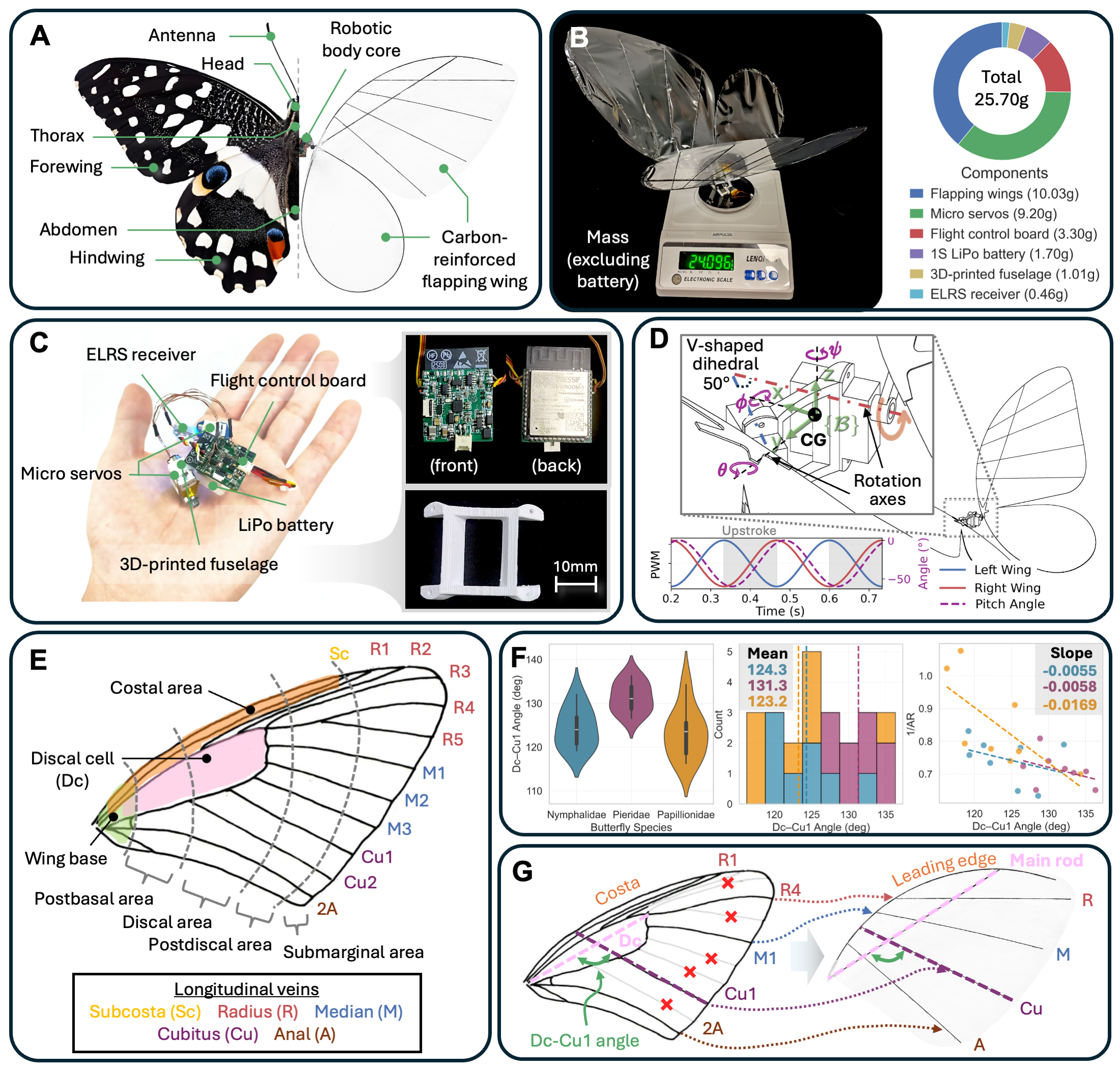
To investigate how butterfly-like wing kinematics and flapping modulation enable controlled free flight, we developed AirPulse (Fig. 1A), a small-scale flapping-wing robot inspired by the lime swallowtail (Papilio demoleus), one of the most widely distributed butterfly species worldwide. To the best of our knowledge, AirPulse is the first and lightest butterfly-inspired flapping-wing platform reported to date with fully integrated onboard sensing and closed-loop control (flight-ready mass 26 g; dry mass 24 g; Fig. 1B and Table 1). The robot was designed as a biological counterpart, being lightweight, morphologically plausible, and instrumented for quantitative studies of aeroelastic wing-air interactions, flapping modulation, and feedback control.
The AirPulse robot features a biomimetic wing structure (wingspan 60 mm) connected to a compact body core (Fig. 1A and movie S1). Its lightweight design was achieved primarily through two complementary strategies. First, we adopted a novel body architecture in which all avionics are directly assembled on a single 3D-printed fuselage (Fig. 1C), unlike previous designs where the control unit or battery was mounted at the abdomen and connected to the thorax via a carbon rod (?, ?, ?, ?). This integration eliminates structural redundancy and allows the Inertial Measurement Unit (IMU) to be co-located near the Center of Gravity (CG). Second, we minimized the wing surface area, yielding the smallest wing planform reported among butterfly-inspired robots in the literature (Table 1). Guided by scaling laws and geometric similarity (?), where and ( is single wing area, is body mass, is characteristic length), we estimated the desired wing size based on the biologically observed mass ratio between wings and body. Specifically, we calculated the non-wing mass and divided it by 0.7, assuming the wings contribute approximately 30% of total mass in butterflies (?). This provided an estimate of the total mass and required wing surface. Starting from a larger prototype capable of generating sufficient lift, we scaled the design accordingly and iteratively refined it through flight tests to identify the minimal wing area that maintained stable lift and control. This iterative process substantially reduced the overall mass while preserving flight capability. As a result, the wings of the AirPulse robot account for approximately 38% of the total body mass (Fig. 1B), comparable to that observed in dried specimens of Papilio xuthus (?), confirming the biological plausibility of the design.
Each lateral wing assembly comprises a forewing and hindwing mechanically coupled via a 3D-printed connector to a common servo arm. Two micro servos mounted on the body core independently actuate the forewings (Fig. 1D), reproducing the anteromotoric wing actuation seen in real butterflies (?). This configuration yields a coupled, synchronous forewing-hindwing motion with a characteristic phase lag (movie S2). For efficient actuation, the servo axes are canted relative to the longitudinal symmetry plane to align the torque transmission with the structural stiff axis. This configuration produces a fixed V-shaped dihedral, realized through the fuselage and servo mounts, which promotes inter-wing force asymmetry similar to that of real butterflies (?). The resulting flapping motion passively induces body undulation with a phase offset between flapping and body pitch angle (Fig. 1D and Fig. 5, F and H). Due to the larger wing-to-body ratio of the robot, this oscillatory coupling is pronounced than in larger robotic fliers (bird-inspired drones), motivating control strategies that explicitly account for periodic body dynamics as discussed later.
The body core houses a custom flight control board featuring a 9-axis IMU and barometer for state estimation, direct Pulse Width Modulation (PWM) servo control, and per-rail current monitoring (Fig. 1C and Materials and Methods). All states are telemetered to the ground station for data logging. The IMU is positioned with the robot’s CG and aligned to the body frame ( forward, left, up) to minimize inertial coupling and aerodynamic interference. A lightweight power management circuit supports both 1S and 2S LiPo batteries, allowing weight reduction with a trade-off in flight endurance.
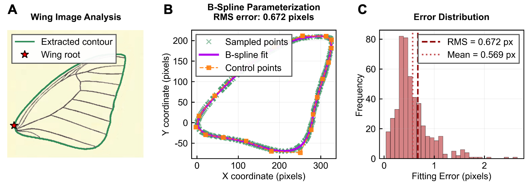
Reducing wing size inevitably decreases lift production, which poses challenges in maintaining efficient flapping flight. To counter these effects, we designed a biomimetic venation-based wing structure. Wings were fabricated from an ultra-thin membrane (polyethylene terephthalate; m thick) reinforced with carbon-fiber rods arranged in a venation-inspired layout, producing a stiffness gradient that balances aerodynamic performance and structural mass. Structural compliance allows passive feathering (aerodynamically driven pitch rotation; movie S2), curtailing active degrees of freedom while maintaining biomechanical plausibility (?). The planform was modeled after swallowtail butterflies using closed periodic cubic B-splines with chord-length parameterization to ensure geometric reproducibility and wing symmetry (fig. S1 and Materials and Methods).
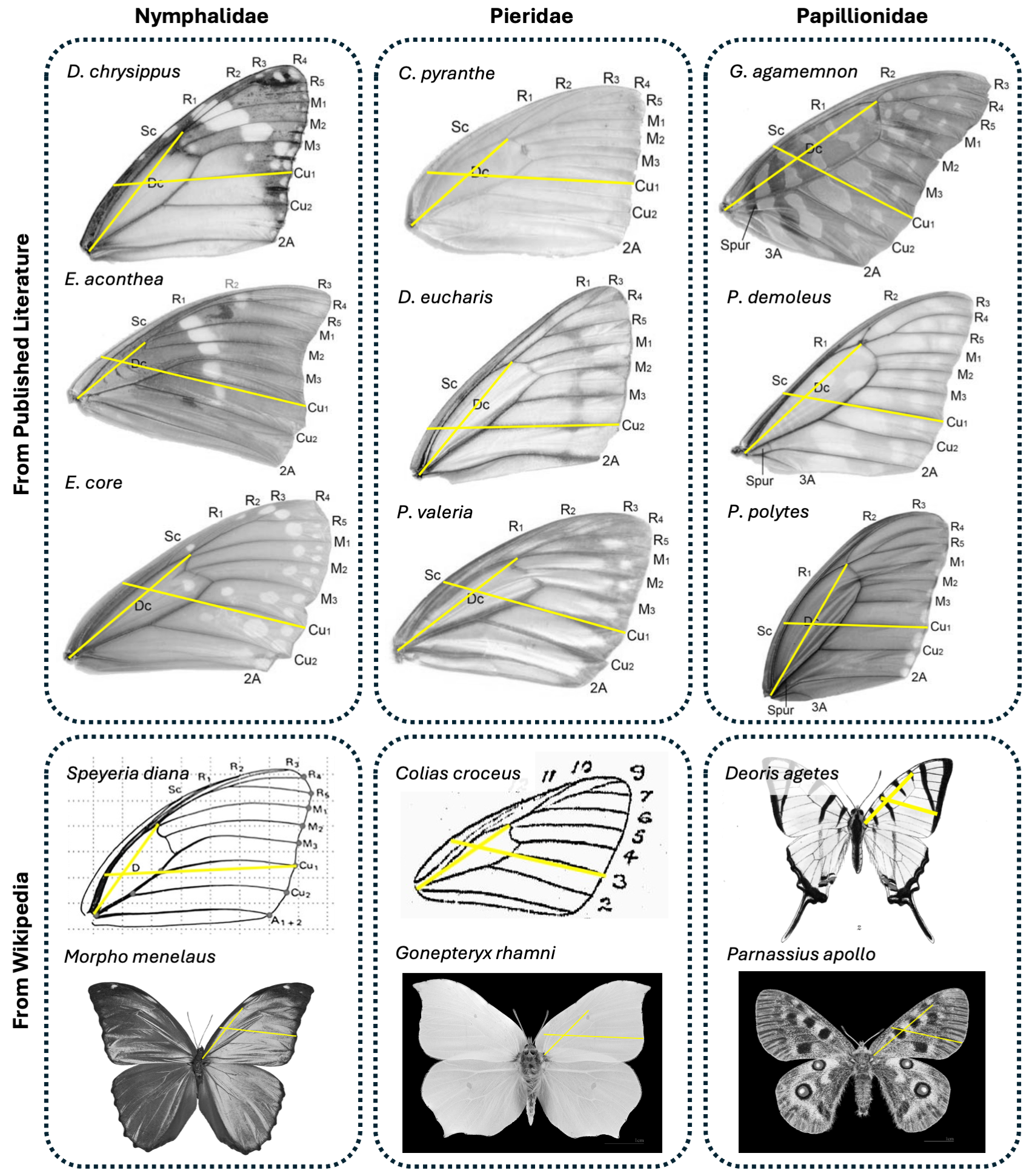
For structural layout, we analyzed the venation morphology across 24 specimens from three major families: Nymphalidae, Pieridae, and Papillionidae (Materials and Methods). Forewing venation typically consists of a discal cell (Dc) and five sets of longitudinal veins—subcostal (Sc), radial (R), medial (M), cubital (Cu), and anal (A)—following the Comstock-Needham system (?) (Fig. 1E). Among families, we found that the Dc-Cu1 angle varied systematically (Fig. 1F and fig. S2): Pieridae showed the largest mean (131.3° ± 3.5°), followed by Nymphalidae (124.3° ± 4.6°) and Papillionidae (123.2° ± 5.8°). Aspect ratio was highest in Papillionidae (0.85 ± 0.14) and lowest in Pieridae (0.71 ± 0.05). Regression analysis revealed a negative correlation between Dc-Cu1 angle and the reciprocal of aspect ratio across all species (slope = –0.0117, = 0.40, = 0.0009), suggesting that larger Dc-Cu1 angles correspond to higher aspect ratios. These morphological couplings indicate that vein geometry influences aerodynamic shape and load-bearing characteristics, serving as principles directly transferrable to biomimetic wing design.
Based on these observations, the AirPulse robot adopted the Dc-Cu1 angle of Papilio demoleus (123°) as the geometric guide for carbon-fiber rod placement for forewings (Fig. 1G). To minimize mass, only one carbon rod was used per major longitudinal vein (R, M, Cu, A branches), an approach supported by evolutionary vein simplification in certain butterfly lineages (e.g., loss of R2 and Cu1 in Delias eucharis). These rods intersect a main spanwise spar anchored from the wing base to tip, forming a discal cell-like structure. The leading-edge rod, together with the main spar and terminal junctions of the longitudinal veins, forms a costal analog that stiffens the anteromotoric region and efficiently transmits flapping torque. Together, these elements form a graded stiffness distribution: rigid costal and basal regions for effective torque transfer, moderately flexible discal area, and compliant distal regions (postdiscal, submarginal) for passive deformation. This compliance gradient closely parallels that of natural butterfly wings and contrasts with prior butterfly-inspired robots, whose venation designs typically rely on triangular reinforcement structures that are not biomechanically representative of real wings (?, ?, ?). For hindwings, we adopted a simplified carbon layout without venation. Prior studies have shown that butterfly hindwings primarily facilitate rapid aerial maneuvers rather than basic flight capabilities (?), making this simplification functionally justified and mass efficient.
Characterization of inertial variation and aerodynamic forces
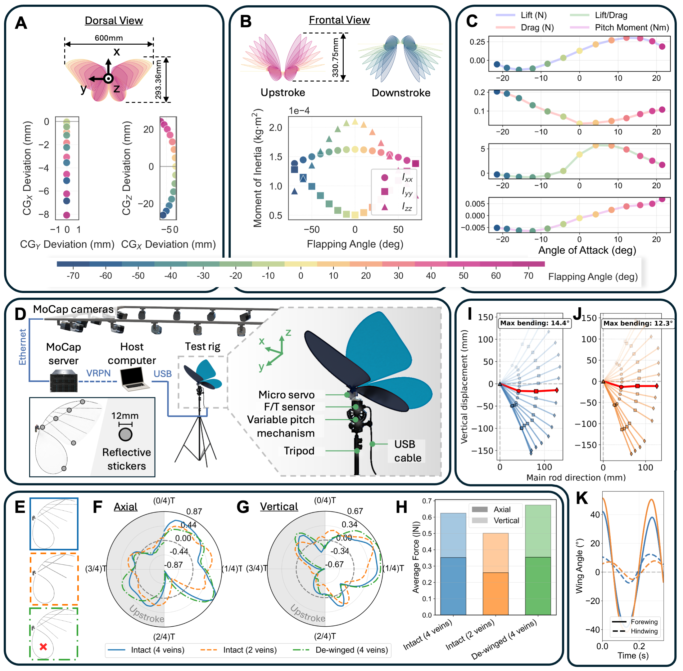
Unlike conventional aerial robots and fast-flapping insects, the AirPulse robot exhibits pronounced body undulation reminiscent of biological butterflies (Fig. 1D and movie S3). This motion originates from the large periodic variation of its inertial properties, which drives a strong coupling between the wing and body dynamics. Experimental measurements reveal that the fore-aft CG shifts by up to of body length, while the vertical displacement reaches approximately twice the body core height (Fig. 2A). Simultaneously, the principal pitch and yaw moments of inertia ( and ) vary by as much as within a single wingstroke (Fig. 2B).
The governing rotational dynamics of FWMAVs follows from the angular-momentum balance,
| (1) |
where represents the coupling between time-varying inertia around body- axis and pitch rotation. In conventional aircrafts, is nearly constant, so and the body responds only to external torques (). In the AirPulse robot, however, changes rapidly as the wings accelerate and decelerate, generating large internal reaction torques even without aerodynamic input. When (wings retracting from to ; Fig. 2B), rotational kinetic energy is drawn from the body to accelerate the wings; when , energy is partially recovered. The alternating exchange of angular momentum between wings and body over successive strokes drives the observed body undulation.
Scaling analyses further explain why the undulatory motion is more prominent at a smaller scale. Aerodynamic torque scales as , while inertial torque scales as , yielding a ratio (where is the characteristic length). Therefore, inertial effects become increasingly dominant as system size decreases. The AirPulse robot operates near this transition regime, where wing inertia is a significant fraction of total body inertia, making non-negligible and leading to large body oscillations. In contrast, larger flapping robots, where wings contribute less to total inertia, exhibit aerodynamically dominated, nearly rigid-body motion.
Static aerodynamic forces and moments (Fig. 2C) were measured directly on the AirPulse robot mounted on a six-axis force-torque (F/T) sensor (BOTA MiniOne; 150 mN force resolution, 1.8 mNm torque resolution), with its CG aligned to the sensor center, installed in an open-circuit wind tunnel (1.8 m 1.2 m 1.0 m, turbulence intensity , blockage ratio ) at a mean wind speed of 3 m/s. Data follow the convention of positive pitching moment as nose-up. Measurements at different flapping angles reveal a positive pitching-moment slope, confirming that the aerodynamic neutral point lies ahead of the CG. This longitudinal static instability enhances pitch responsiveness but implies that sustained flight cannot rely on passive aerodynamic stability and requires active control. Static lift measurements show a peak of 0.292 N at a flapping angle, exceeding the body weight of 0.26 N and allowing for gliding behavior. Nonetheless, static measurements cannot ensure sufficient lift during flapping flight maneuvers such as climbing or turning, where unsteady aerodynamic effects dominate.
To elucidate how flapping-wing morphology influences aerodynamic force generation, we examined the aeroelastic behavior of butterfly-inspired wings characterized by broad planforms and vein-reinforced membranes. Such wings exhibit spatially heterogeneous stiffness arising from their intricate venation, which produces complex, phase-dependent deformations during flapping. This contrasts with the more uniform rod-reinforced wings commonly used in Diptera- or hummingbird-inspired robots (?, ?), where structural compliance is largely homogeneous. The venation-driven stiffness distribution in butterflies thus provides a natural mechanism for modulating local angle of attack and instantaneous force production throughout the wingstroke. To experimentally assess these effects, three wing variants were fabricated (Fig. 2E): (i) intact forewings with four longitudinal veins (R, M, Cu, A), (ii) intact forewings with two reduced reinforcement, and (iii) forewings with four veins paired with de-winged hindwings (hindwing membrane removed). The third variant isolates hindwing contributions, motivated by observations that hindwings primarily enhance maneuverability rather than generate essential lift (?).
Each wing variant was evaluated on a test platform (Fig. 2D) equipped with the aforementioned six-axis load cell along with a retroreflective-marker-based motion capture system (LUSTER FZMotion). Aerodynamic forces were obtained by subtracting inertial contributions (Materials and Methods). Results show that intact and de-winged four-vein wings produce similar in-cycle force profiles (Fig. 2, F and G), whereas two-vein wings exhibit distinct axial and vertical force patterns, indicating phase shifts caused by increased structural compliance. Furthermore, intact four-vein wings generate larger cycle-averaged axial and vertical forces than two-vein wings, but slightly lower than de-winged variants (Fig. 2H). This outcome likely reflects that the hindwing, in the current configuration, is neither biomimetically aligned with the forewing nor designed with a proper stiffness gradient. As a result, it flaps about an aerodynamically suboptimal axis, inducing additional drag and disrupting forewing wake flow. Wing deformation analysis reveals comparable flapping amplitudes and maximum bending angles (14.4° and 12.3°) near the downstroke horizontal position for intact four-vein and two-vein wings (Fig. 2, I and J). However, two-vein wings display a larger chordwise deflection of the forewing (Fig. 2K), confirming higher compliance in distal regions. These findings align with prior studies showing that trailing-edge flexibility reduces aerodynamic force in flexible wings with isotropic materials and simplified venation (?).
Stroke timing asymmetry rhythm: a smooth and stable flapping pattern
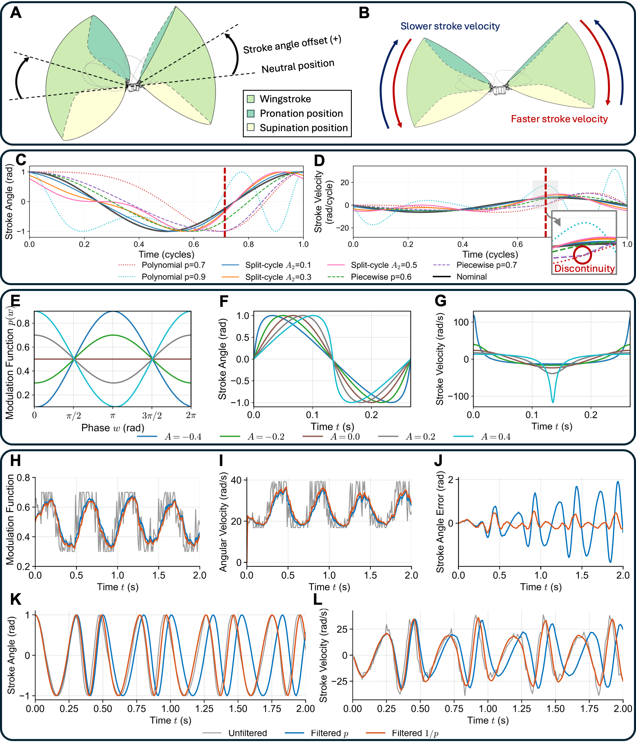
Generating aerodynamic moments on small flapping-wing robots requires low-dimensional modulation that is both numerically stable and kinematically smooth, particularly ensuring continuity of the first derivative of stroke angle, while maintaining mechanical simplicity. Biological fliers achieve this largely via subtle modulations of wingstroke kinematics (?). In engineering practice, three principal kinematic strategies are commonly employed for generating periodic signals: stroke amplitude modulation (less common mechanism in real insect flight control), stroke angle offset modulation (shifting the neutral position, and therefore, the stroke plane; Fig. 3A), and stroke timing or velocity modulation (Fig. 3B). The first two approaches are straightforward and widely employed (?, ?, ?). In contrast, stroke timing modulation generates asymmetric upstroke and downstroke velocities within a single wingbeat. This asymmetry produces a nonzero cycle-averaged drag force on each wing while maintaining stroke amplitude. Despite its biological relevance for rapid maneuvers such as body saccades, it has received comparatively few systematic studies.
Existing stroke timing modulation schemes face a trade-off between stability and smoothness (Fig. 3, C and D). Polynomial phase-shaping methods yield differentiable kinematics but permit only limited up-down stroke asymmetry and become sensitive when parameters exit a narrow admissible range (?), which may result in erroneous flapping behavior. Split-cycle strategies allow larger asymmetry but introduce either instability when modulation exceeds feasible limits (?) or kinematic discontinuities at switching points (?, ?), which risk actuator saturation and structural excitation. These limitations motivate a stroke timing modulation law that ensures at least first-derivative continuity while expanding the range of attainable asymmetry in a stable manner.
We introduce Stroke Timing Asymmetry Rhythm (STAR), a single-parameter phase-domain rhythm generator that guarantees continuous phase speed and smooth first derivatives, producing bounded, monotonic up–down stroke asymmetry (Fig. 3, E to G). With the phase origin at mid-downstroke (), STAR is defined as
| (2) |
where is the flapping amplitude, is the nominal flapping frequency, and is the dimensionless modulation parameter for asymmetric stroke timing whose admissible range can be linearly normalized to for convenience. The cosine form of the modulation function is chosen to suppress phase offsets arising from initial errors (Supplementary Text). This formulation provides three guarantees (Materials and Methods): (i) the cycle-averaged frequency is exactly preserved for any constant , allowing intra-cycle timing to be skewed without altering mean rate; (ii) stroke asymmetry scales linearly and monotonically with , yielding a simple yet direct tuning rule; (iii) both stroke angle and its first derivative remain continuous, preventing abrupt accelerations that could saturate actuators or excite structural vibrations.
To ensure smooth transients under time-varying control commands, we apply an Infinite Impulse Response (IIR) filter to the reciprocal variable rather than itself (Fig. 3, H and I, and Materials and Methods). Since phase update is linear in , filtering this variable preserves an unbiased mapping between the control input and phase increment (Fig. 3, J to L). Filtering instead would introduce nonlinear distortion and cumulative phase drift, corrupting stroke timing and reducing control effectiveness.
Compared to prior stroke timing methods, STAR provides a principled and analytically tractable law that simultaneously ensures: (i) bounded and continuous phase speed and smooth first-derivative kinematics; (ii) exact preservation of mean flapping frequency; and (iii) a single parameter that produces large and monotonic up-down asymmetry within provable bounds. These properties eliminate the main failure modes of earlier schemes such as discontinuous derivatives, narrow stability margins, and non-periodic or erratic phase trajectories. Consequently, STAR is mathematically grounded, practically stable, and well suited for small-scale, actuator-limited flapping-wing platforms.
Mapping forces and torques from flapping kinematics
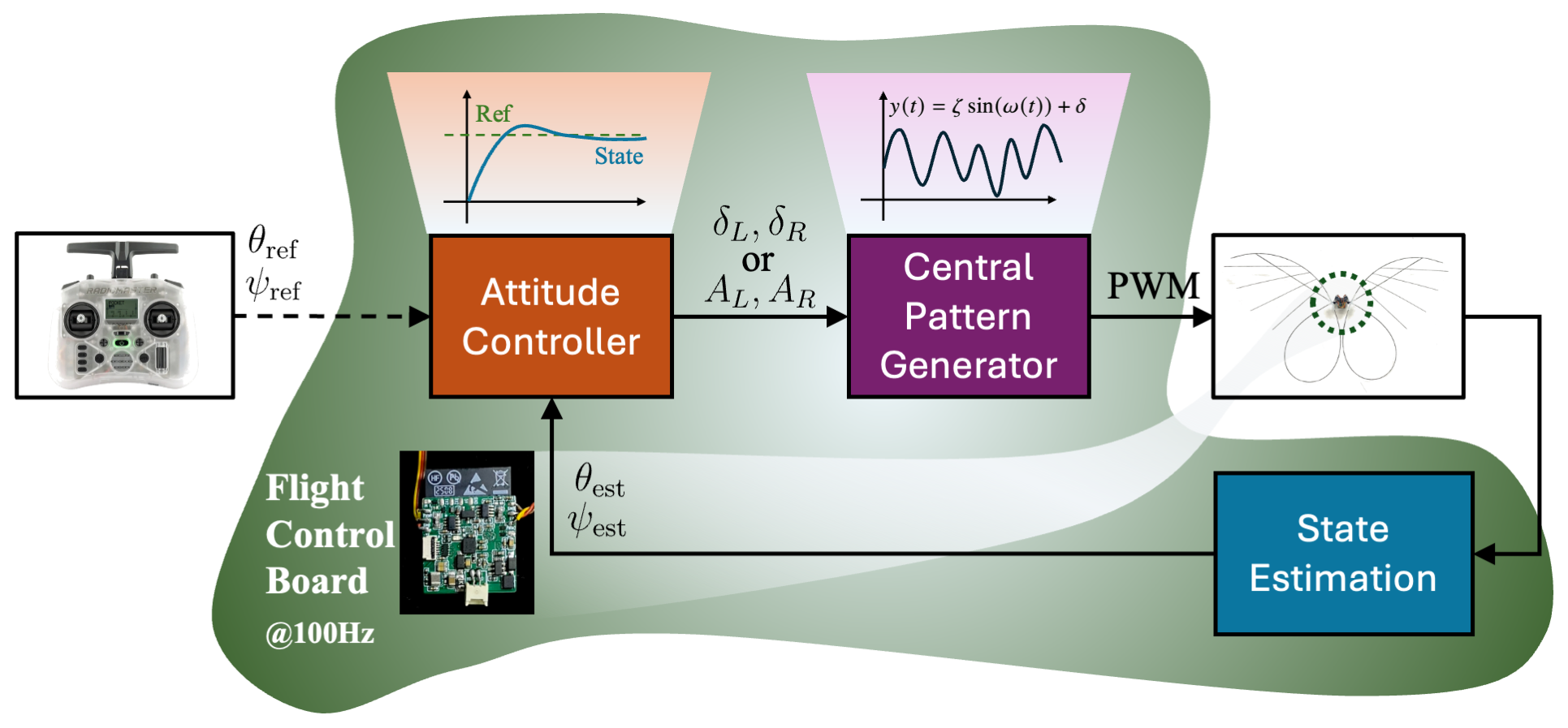
The flapping motion of biological butterflies is governed by Central Pattern Generators, neural circuits that generate rhythmic motor outputs without the need for rhythmic inputs. These networks exhibit strong adaptability, as their intrinsic neuronal properties and synaptic connections can be dynamically modulated through sensory feedback. Following this biological principle, we implemented a sinusoidal oscillator incorporating STAR, described by
| (3) |
where denotes the stroke angle offset and other variables are defined in (2). While Hopf oscillators are commonly used for robotic CPGs, they primarily ensure rhythmic stability during amplitude transitions with fixed phase velocity (?). This property contrasts with insect flight, where differential stroke timing rather than amplitude modulation alone serves as the primary control mechanism. The sinusoidal oscillator with STAR (3) captures this mechanism directly, producing wing kinematics that more closely resemble those of real insects. The oscillator output drives two micro servos via PWM signals, allowing independent control of the left and right wings. The main modulatory parameters include flapping frequency , amplitude , angle offset , and the STAR parameter , which determines stroke timing asymmetry.
A central challenge in designing flapping-wing robots is to determine how modulatory parameters (or control inputs) translate into measurable forces and torques, thereby enabling effective control allocation and accurate dynamical modeling. This challenge is particularly evident in the AirPulse robot, which operates with only two actuators in a 6-DOF workspace. Such underactuation poses a complex control-allocation problem, as limited inputs must generate coupled and nonlinear force-torque responses across multiple axes. Existing studies on butterfly-inspired robots (?, ?, ?, ?, ?) rarely provide systematic quantification of these relationships, leaving the connection between flapping modulation and the resulting dynamic behavior insufficiently understood.
To establish a quantitative foundation for controller design, we performed a series of experiments measuring the total flapping-induced forces and torques using the test rig (Fig. 2D). While theoretical models exist such as quasi-steady ones based on instantaneous forces and kinematic parameters (?, ?, ?), unsteady mechanisms such as Leading-Edge Vortexs, rotational circulation, wake interference, and structural flexure render these first-principles modeling intractable for heterogeneous wing architectures (?). Furthermore, the system’s strong sensitivity to kinematic variations, combined with unsteady aerodynamic effects, renders analytical control design overly sophisticated. The empirical approach therefore captures the complete set of physical effects, providing direct measurements that inherently incorporate aerodynamic-inertial coupling often neglected in simplified theoretical formulations.
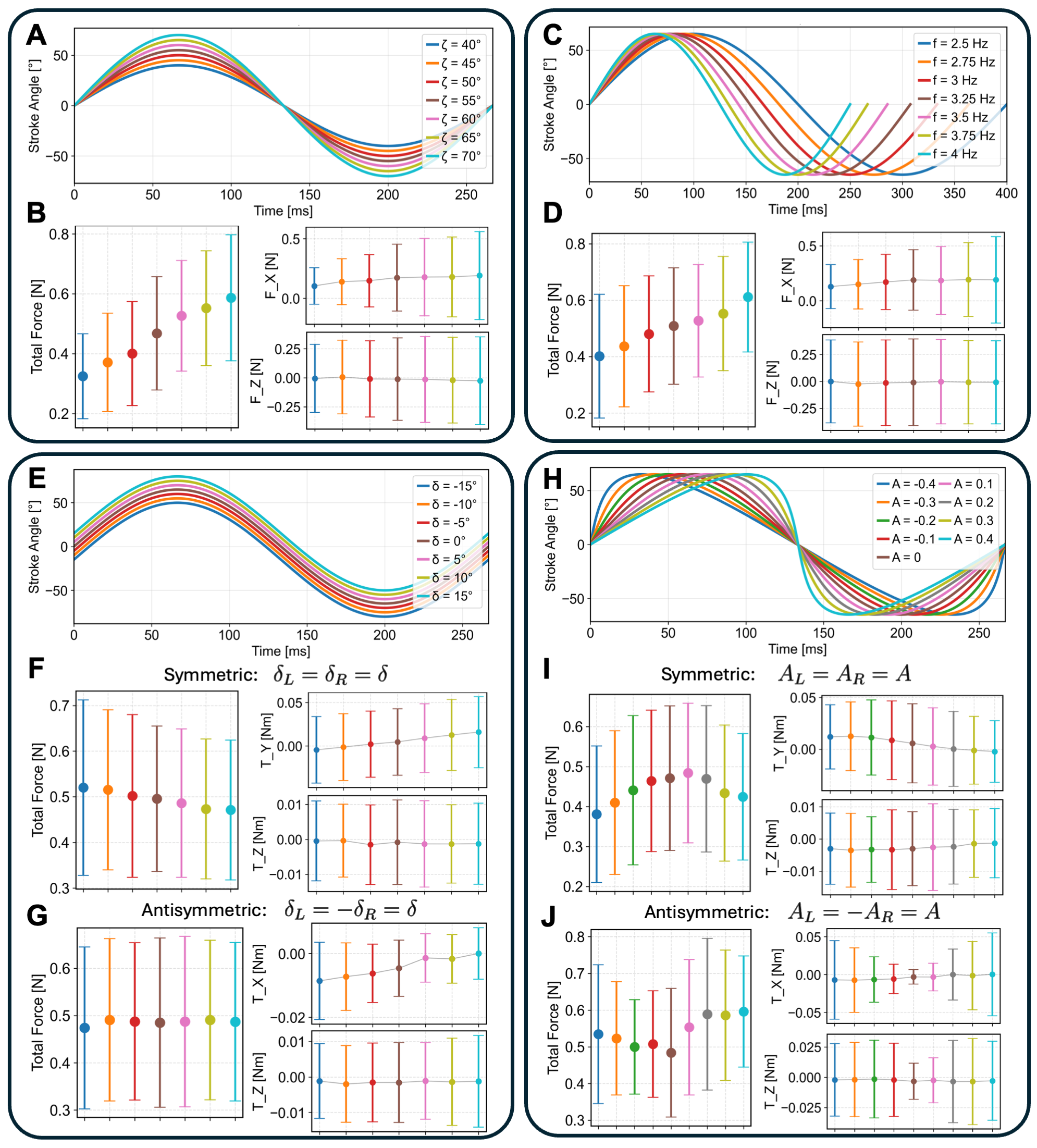
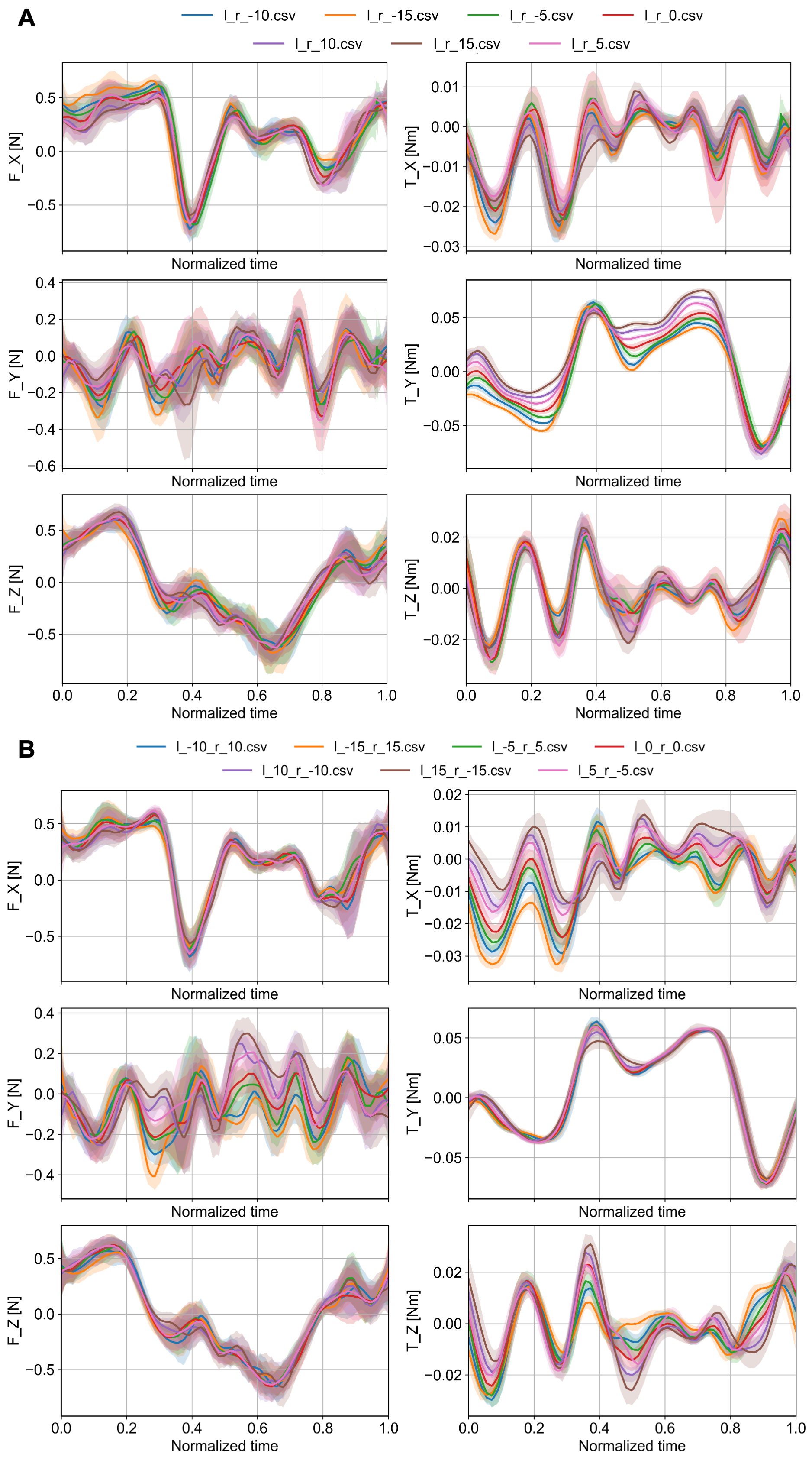
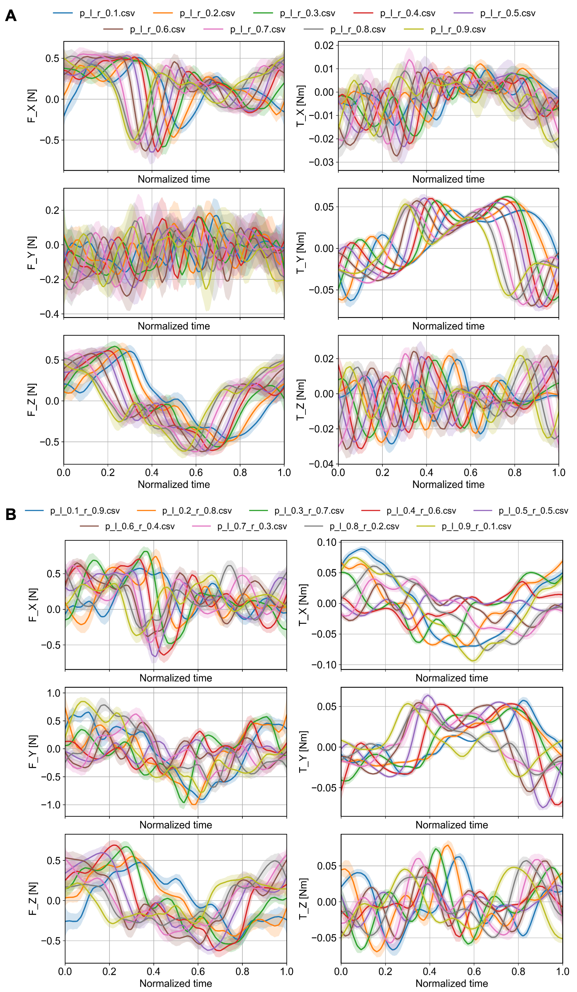
Six experimental campaigns systematically varied the key control parameters, including flapping amplitude (Fig. 4, A and B), flapping frequency (Fig. 4, C and D), symmetric and antisymmetric angle offset modulation (Fig. 4, E to G), and symmetric and antisymmetric stroke timing modulation through the STAR parameter (Fig. 4, H to J). For each configuration, total forces and torques were recorded along all three body axes over 80 wingbeats, and the middle 40 cycles were analyzed to eliminate transient effects. Each data point in the plots represents the mean of the cycle-averaged values, with error bars denoting standard deviations across cycles. Larger standard deviations indicate stronger within-cycle variations in the periodic forces and torques. The force-torque reference frame is defined to be parallel to the body frame of the robot (Fig. 2D).
Results show that increasing either flapping amplitude or frequency consistently enhances total force generation, predominantly along the forward (body-) axis (Fig. 4, B and D), with minimal effect on mean torque. This suggests that amplitude and frequency modulation primarily regulate flight speed rather than orientation, while also potentially improving maneuverability by enabling larger accelerations during rapid maneuvers such as sharp turns.
Angle offset modulation exhibits more nuanced control authority. Symmetric increases in (both wings shifting upward; Fig. 3A) reduce total force while generating progressively larger pitch moments (Fig. 4F), resulting in nose-down torques consistent with free-flight observations. This confirms that symmetric angle offset modulation functions as a reliable mechanism for pitch control. In contrast, antisymmetric offset modulation (opposite shifts of the left and right wings) produces minimal changes in total force or yaw torque but induces pronounced roll moments when the left wing elevates and the right wing descends (Fig. 4G). Interestingly, this behavior seemingly contrasts with free-flight maneuvers, where the same configuration produces left turns. This indicates a fundamentally different turning mechanism from that of fixed-wing aircraft, in which roll moments generate banked turns. For the AirPulse robot, turning is likely initiated by adverse yaw, created when one wing experiences greater drag during the downstroke, yawing the robot’s nose toward that side. This yaw motion subsequently induces a sideslip in the opposite direction, which, together with the wing’s dihedral angle, produces a secondary rolling moment. Hence, the roll observed in flight is a consequence of yaw rather than its cause. This mechanism is empirically supported by free-flight observations, where roll excursions during turning remain small, indicating that the maneuver is primarily yaw-driven, similar to previously reported yaw turns in dragonflies (?). The observed roll may even occasionally occur in the opposite direction (a slight right roll during a left turn) or lag behind the yaw motion. Overall, antisymmetric angle offset modulation proves to be an effective and practical strategy for executing turning maneuvers.
Compared with previous modulation methods, stroke timing modulation via the STAR parameter exhibits distinct force-torque characteristics. Symmetric increases in (faster downstroke and slower upstroke; Fig. 3B) decrease mean pitch torque, generating a nose-up moment and establishing stroke timing as a complementary mechanism for pitch control alongside angle offset modulation (Fig. 4I). Antisymmetric modulation (asynchronous timing between wings) produces pronounced roll moments with minor yaw torque variations (Fig. 4J), consistently resulting in right-turn maneuvers confirmed in free-flight tests. Notably, STAR-based modulation shows greater variance in force and torque profiles than angle offset modulation, indicating phase-dependent alterations in periodic force generation (fig. S4) rather than amplitude-driven differences (fig. S3).
These results highlight the complementary roles of angle offset and stroke timing modulation. Angle offset modulation primarily scales the magnitude of forces, whereas stroke timing modulation adjusts their phase within each wingstroke. The variance patterns support this distinction: STAR modulation alters the temporal phasing of instantaneous forces, while offset modulation changes their amplitude without affecting timing. These findings establish a quantitative mapping between modulation parameters and dynamic responses, forming a basis for hierarchical control architectures in which high-level commands modulate CPG parameters to achieve desired force-torque profiles.
Demonstration of undulatory free flight with attitude stabilization
Building on the established mapping between flapping modulation and force-torque generation, we developed a control architecture for free flight (fig. S5) composed of three modules: state estimator, attitude controller and CPG (Supplementary Text). The state estimator fuses raw IMU signals using a Madgwick filter, providing drift-compensated attitude estimates on a resource-constrained hardware in real time. These estimates are processed by an attitude controller based PID, which computes errors from the desired references and outputs modulatory commands to the CPG. Lastly, CPG converts these commands into periodic flapping PWM signals, independently driving the two micro servos to achieve differential wing modulation between the left and right wings. In contrast to fast-flapping robots in the literature (?, ?, ?, ?), which can be effectively controlled using stroke-averaged models, the AirPulse robot exhibits strong dynamic coupling between its low-frequency flapping and body undulation (Fig. 1D and Fig. 5, F and H). This coupling violates the core assumption of timescale separation, rendering the conventional stroke-averaged approach invalid for our platform (?).
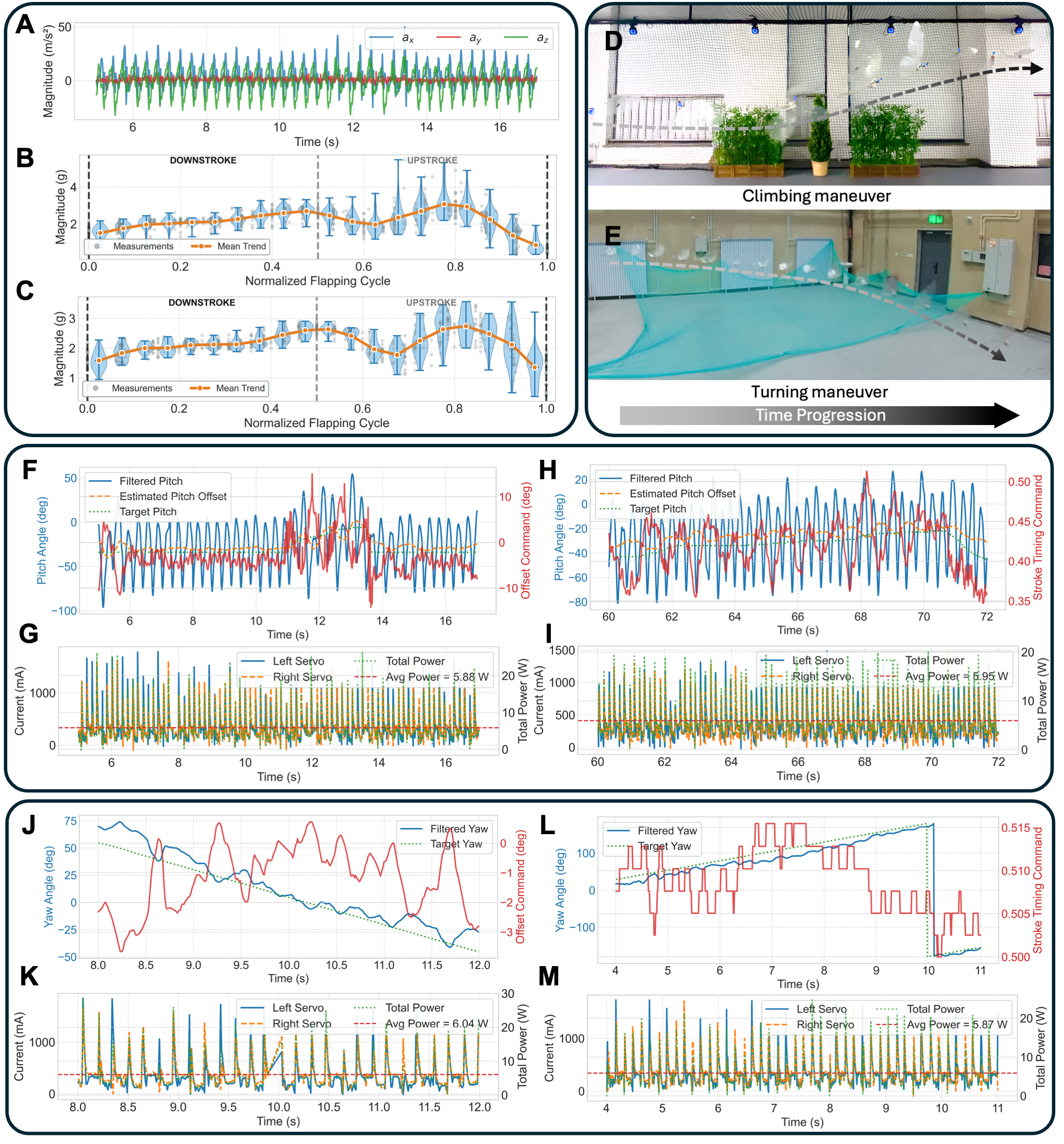
A fundamental challenge in the free flight of the AirPulse robot is the strong periodic variation of inertial and aerodynamic forces, which induces large pitch oscillations around (Fig. 5F) and produces the characteristic undulatory motion also observed in real butterflies (movie S3). Unlike conventional aerial vehicles that rely on static equilibrium, the robot must operate in a dynamically unsteady regime where attitude and propulsion are tightly coupled within each flapping cycle. This phenomenon was experimentally verified through tri-axial accelerometer data (Fig. 5A), which revealed sustained forward acceleration ( g) together with pronounced vertical oscillations ( g). The overall acceleration magnitude ( g, peaking at 5.475 g) exhibited rhythmic variations consistent with cyclic energy exchange between lift generation and forward thrust. These measurements confirm that forward flight in the AirPulse robot arises from aerodynamic-inertial coupling, a regime where mechanical energy is periodically redistributed rather than continuously applied, thereby mirroring the dynamic efficiency of natural butterfly flight. Interestingly, we observed that both angle offset and stroke timing modulations produced comparable intra-cycle acceleration profiles (Fig. 5, B and C), characterized by a rise during downstroke, a minor drop at the start of upstroke, and a second peak of similar amplitude before descending again. This signifies coordinated phasing between aerodynamic force and body motion. Because these oscillatory dynamics propagate into the pitch signal, direct feedback control without filtering would yield oscillatory control commands, structural fatigue, or even instability.
To achieve stable attitude regulation within this oscillatory regime, we employed an online estimation algorithm based on Recursive Least Squares (RLS) (Materials and Methods) that adaptively extracts the low-frequency mean of the pitch signal (Fig. 5, F and H). The estimated signal serves as a control-effective surrogate of the oscillatory pitch angle, enabling the computation of stable error and non-oscillatory control commands. Two complementary control pathways, namely angle offset and stroke timing modulation, were evaluated in free-flight experiments, demonstrating how distinct phase and amplitude control channels can be exploited to achieve climbing and turning maneuvers (Fig. 5, D and E; movies S4 and S5). Both modulation strategies achieved accurate pitch tracking by adjusting either the stroke offset (Fig. 5, F and G) or the stroke timing (Fig. 5, H and I), consistent with the force-torque relationships established in experimental characterization. Average power consumption remained low (5.88 W and 5.95 W, respectively), underscoring the energetic efficiency of the flapping mechanism. For directional control, yaw was selected as the primary variable because free-flight tests showed that turning arises from coupled roll-yaw dynamics, with roll excursions remaining minor. Stable turns were achieved using either modulation strategies (Fig. 5, J and L), with comparable power requirements (6.04 W and 5.87 W; Fig. 5, K and M). Compared to micro quadrotors (?), which draw approximately 10.6 W in hover, these results demonstrate that the AirPulse robot attains forward flight with substantially lower power demand, revealing the aerodynamic efficiency of dynamically coupled flapping-wing motion. These experiments validate a closed-loop control framework that integrates flapping kinematics, state estimation, and phase-coordinated modulation of wing motion to achieve stable undulatory free flight.
Discussion
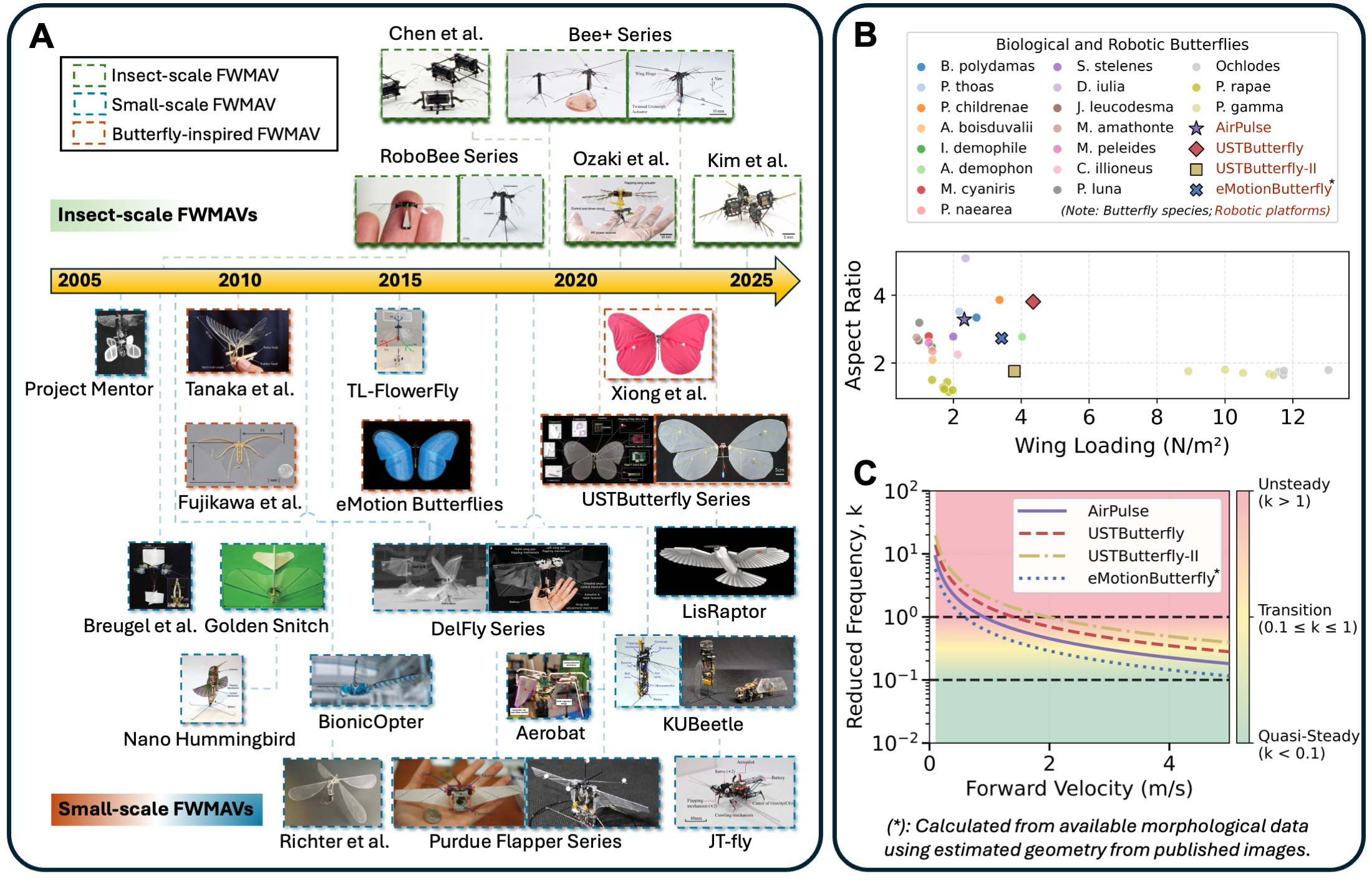
The present study demonstrates the first and lightest untethered flight of a butterfly-inspired, two-winged, tailless flapping-wing robot, AirPulse, in the peer-reviewed literature (Fig. 6A and Table 1), capable of executing climbing and turning maneuvers using only onboard sensing and control. The 26 g platform employs two micro servos to drive low-aspect-ratio wings with biomimetic venation, reproducing the heterogeneous stiffness distribution characteristic of real butterfly wings. Through systematic force-torque mapping, we identified how flapping parameters—including amplitude, frequency, stroke angle offset, and stroke timing—govern the generation of aerodynamic and inertial forces. Building upon these insights, we developed a flight controller that accounts for body undulation caused by cyclic variations in the inertial properties. This controller achieves stable pitch and yaw tracking via two complementary modulation strategies: angle offset control, and our proposed phase-domain rhythm generator (STAR) that enables smooth and stable modulation of stroke timing asymmetry.
The AirPulse robot demonstrates strong biological relevance to real butterfly flight, for instance, closely matching the swallowtail butterfly (Papilio thoas) in the ratio between aspect ratio (, where is wingspan and is single wing area) and wing loading (, where is body mass) (Fig. 6B). Notably, its wing loading is among the lowest in previously reported butterfly-inspired robots (?, ?) (Table 1), suggesting improved aerodynamic efficiency, enhanced maneuverability, and the ability to sustain low-speed flight (?). The aerodynamic regime of the AirPulse robot was quantified by its Reynolds number, calculated as , based on a mean aerodynamic chord of mm and characteristic velocity m/s. This regime aligns with biological counterparts such as Vanessa cardui () (?), confirming that the robot operates within the same viscous, low-Reynolds number region where unsteady mechanisms, including LEV formation, rotational lift, and wake capture, dominate aerodynamic force generation. In contrast, conventional rotary-wing robots of comparable scale typically operate at , where airflow remains largely attached and steady. The AirPulse robot thus represents a fundamentally different aerodynamic paradigm that is highly reliant on vortex-dominated flow physics rather than quasi-steady lift generation.
To further elucidate the aerodynamic operating regime of the AirPulse robot, we analyzed the reduced frequency, defined as , where is the flapping angular velocity, is the mean chord length, and is the forward flight speed. By inverting this relation, we estimated the corresponding forward velocity range for given values, thereby identifying the aerodynamic transition between quasi-steady () and unsteady () regimes (Fig. 6C). The results further confirm that, for working flapping frequencies and chord dimensions, the AirPulse robot operates predominantly in the unsteady to transitional region, where vortex-dominated mechanisms play a central role in lift generation. Moreover, consistent with prior findings (?), aerodynamic efficiency increases with decreasing reduced frequency or non-dimensional wing loading, implying that the AirPulse robot not only reproduces key aerodynamic features of butterfly flight but also provides a controlled and measurable testbed for investigating the coupled inertial-aerodynamic mechanisms within a biologically relevant regime comparable to that of real butterflies (?, ?).
Despite these advances, several limitations and open challenges remain. The current PID-based controller, while effective in stabilizing pitch and yaw, requires empirical gain tuning and lacks sufficient robustness under dynamically varying aerodynamic loads or exogenous disturbances. The strong fluid-structure coupling intrinsic to flexible wings introduces additional nonlinearities that are not fully captured by classical control frameworks. Developing higher-fidelity dynamic models (especially from wing kinematics to force-torque generation) remains an active area of investigation, essential for the design of advanced controllers such as adaptive, model-based, or neural control architectures (?). Furthermore, while our biomimetic venation design reflects spatial stiffness distribution, the influence of interspecific venation angles and vein topology on aerodynamic performance remains unresolved. Current datasets are insufficient to statistically determine whether observed angle variations across species represent evolutionary features or random morphological variance. Broader interdisciplinary efforts combining biological morphology, computational modeling, and robotic validation will be necessary to uncover such correlations. Our future work will also focus on integrating neuromorphic architectures to couple event-driven sensory modalities such as dynamic vision (?) and olfactory cues (?) for navigation and localization in cluttered or GPS-denied environments. Incorporating such sensory-motor integration may ultimately allow flapping-wing robots to exhibit autonomous behaviors comparable to real insects, bridging the gap between biological and engineered flight systems.
| Robot | eMotionButterfly (?) | USTButterfly-II (?) | USTButterfly (?) | AirPulse (Ours) |
|---|---|---|---|---|
| Year | 2015 | 2022 | 2024 | 2025 |
| Weight (, g) | 32 | 54 | 107.1 | 26 |
| Wingspan (, cm) | 50 | 50 | 90 | 60 |
| Aspect Ratio () | 2.73∗ | 1.76∗ | 3.81† | 3.28 |
| Wing Area (, mm2) | 45 861.9∗∗ | 71 052.6∗ | 123 184.3 | 54 916.8 |
| Wing Loading (, N m-2) | 3.42∗ | 3.80 | 4.35 | 2.32 |
∗Calculated from available morphological data. ∗∗Estimated from geometry using published images. †Reported as 3.81 in (?), though calculated value gives using the listed dimensions.
References and Notes
Acknowledgments
We are grateful to Prof. G.C.H.E. de Croon, Prof. Maurizio Porfiri, and Prof. Lu Fang for their insightful comments and feedback on this manuscript. W.G. acknowledges support from the China Postdoctoral Science Foundation under Grant Number 2025M781650 and the Shuimu Scholar Program of Tsinghua University under Grant Number 2024SM224. This work was also supported by Xinchen Qihang Inc.
Funding:
Not applicable.
Author contributions:
W.G. conceived the ideas, designed the robots and test apparatus. C.F. and X.J. designed the electronics. L.L. and X.S. designed the mechanical structure. W.G., C.F., C.Y., and Y.D. devised the control algorithm. C.F. and Y.D. developed the ground control station and visualization software. W.G., C.F., L.L., C.Y., X.J., Y.D., and X.S. performed the experiments. W.G., C.F., and L.L. conducted data analysis. W.G. and L.L. prepared the figures and movies. W.G. wrote and revised the manuscript. C.G. advised the robot design, experiments, and manuscript. A.R. and G.Z. advised the manuscript.
Competing interests:
The authors declare that they have no competing interests.
Data and materials availability:
All data needed to support the conclusions of this manuscript are included in the main text or the Supplementary Materials. The data for this study are temporarily available in a GitHub repository at https://github.com/wgu93/AirPulse_Paper_Figs_and_Data.git and will be permanently archived in Zenodo upon acceptance of the manuscript.
Supplementary materials
Materials and Methods
Supplementary Text
Figs. S1 to S5
Tables S1 to S2
References (78-0)
Movie S1 to S5
Supplementary Materials for
A 26-Gram Butterfly-Inspired Robot Achieving Autonomous Tailless Flight
Weibin Gu et al.
Corresponding authors: Chao Gao, Guyue Zhou
Email: chao.gao@cantab.net, zhouguyue@air.tsinghua.edu.cn
This PDF file includes:
Materials and Methods
Supplementary Text
Figures S1 to S5
Tables S1 to S2
Captions for Movies S1 to S5
Other Supplementary Materials for this manuscript:
Movies S1 to S5
Materials and Methods
Fabrication of robot components
The fuselage and wing-servo connectors were 3D printed in polyethylene terephthalate glycol (PETG) using fused-deposition modeling. PETG was selected over polylactic acid (PLA) and thermoplastic polyurethane (TPU) for its combination of rigidity and impact resistance, allowing the structure to endure cyclic inertial loads during sustained flapping.
Wings were fabricated from Mylar film reinforced with carbon fiber spars (a 1.0 mm main spar, 0.8 mm leading edge and hindwing contour, and 0.5 mm longitudinal veins). The carbon reinforcement provided a high stiffness-to-weight ratio and enabled spatial stiffness gradients analogous to those found in butterfly wings. Alternative membranes were evaluated: TPU exhibited excessive compliance and poor adhesion, while silicone-coated polyamide (PA66) offered durability but imposed excessive mass. All tested membranes were flight-capable; however, PET was ultimately chosen for its balance of light weight, stiffness, tear resistance, adhesive compatibility, and optical transparency for motion capture. Wing fabrication involved laser-printing a venation template, overlaying the PET film, and bonding carbon rods using UV-curable adhesive and cyanoacrylate. Left-right wing pairs were mass-balanced within 0.05 g ( of a single wing mass) to minimize asymmetries that could induce unbalanced aerodynamic forces or fuselage vibrations from uneven stroke timing or deformation (?).
Commercial micro servos (BlueArrow D30T MG HV, 4.6 g each) were selected for their high torque-to-weight ratio and metal geartrain, minimizing backlash under dynamic loading. Metal servo arms were used to prevent torsional deformation observed with plastic arms, which degraded stroke symmetry and amplitude. Although lighter custom actuators with planetary gearboxes could further reduce mass, off-the-shelf servos were preferred for their reliability, reproducibility, and ease of integration.
The onboard embedded system is based on an ESP32-S3-WROOM-1-N16R8 (dual-core 32-bit Xtensa LX7, 240 MHz, 16 MB Flash, 8 MB PSRAM), supporting parallel real-time wing actuation and wireless communication with a custom ground control station for data logging and monitoring. Power is supplied by 1S or 2S LiPo batteries through a multi-stage regulation system: a buck converter provides 3.3 V to the controller and sensors, a boost circuit delivers 8.2 V to the servos for consistent torque under high load, and an LDO outputs 5 V to the ExpressLRS module. The ELRS module serves only as a safety override for manual control. Servo current and power consumption are monitored via INA219 sensors. The sensor suite includes an ICM-42688-P IMU (±16 g, ±2000 °/s, 32 kHz), BMM350 magnetometer (±2000 T, 400 Hz), and BMP390L barometer (±3 Pa, 200 Hz) for real-time state estimation.
Forewing contour parameterization
Sampled wing contour (data points ) were represented by a periodic cubic B-spline. The spline curve is defined as
| (S1) |
where are the spline control points determined by smoothing least-squares fitting, and are the cubic B-spline basis functions defined by the Cox-deBoor recursion (?) as
| (S2) | ||||
| (S3) |
with the convention that any fraction with a zero denominator is taken as zero. A periodic knot vector was used to ensure closure and continuity.
Raw contours were cyclically reordered to start at the wing root and closed by appending the start point (fig. S1A). Parameter values were assigned by chord length as
| (S4) |
and a periodic smoothing cubic spline was fitted to by least-squares with smoothing factor ( herein). The fitted spline was resampled at uniformly spaced to yield a dense curve . Fit quality was quantified by nearest-neighbor errors as
| (S5) |
The parameterization results from the above analysis were reported in Table S1 and the control points for the forewing spline representation were summarized in Table S2. The fitting procedure achieved an RMS error of 0.672 pixels (fig. S1B), corresponding to a relative error of 0.13% of the wing span. The error distribution (fig. S1C) shows that 95% of contour points were fitted with errors less than 1.5 pixels, demonstrating the high accuracy of the B-spline representation while maintaining continuity. This parameterization procedure produced smooth, reproducible wing contours suitable for CAD modeling and aeroelastic analysis, with the compact control point representation enabling efficient computational modeling while preserving biological accuracy.
Biological wing venation analysis
Forewing images were collected primarily from published literature with documented clear venation patterns (?), supplemented by photographs of museum-grade specimens available from open-access sources (Wikipedia). Specimens were selected based on strict visibility criteria requiring a fully unobstructed forewing (dorsal or ventral) view with distinct Dc and Cu1 veins, which define key geometric axes for comparative analysis. The dense and pigmented scales on butterfly wings often obscure vein boundaries, substantially constraining the number of usable samples. Consequently, the final dataset included 24 different specimens representing three families, namely Nymphalidae (), Pieridae (), and Papillionidae (). For each specimen, the forewing image was first converted to grayscale and manually annotated with yellow solid lines indicating the Dc and Cu1 veins (fig. S2). The annotated regions were then segmented in HSV color space to extract the obtuse inter-vein Dc-Cu1 angle. Future morphological studies could expand statistical results by employing chemical bleaching or depigmentation techniques to enhance venation contrast and enable automated image segmentation.
Wing performance analysis
Wing performance was assessed using a custom flapping apparatus (Fig. 2D). Retroreflective stickers were selected for their low mass, which is the lightest available option despite still adding some weight. Increasing the number or size of markers could improve tracking accuracy but would also alter wing dynamics due to extra weight. Each wing variant underwent same flapping cycles while synchronized force and kinematic data were recorded at 222 Hz. The raw force signals were processed through a computational pipeline that first identified active flapping periods by detecting servo motor activation thresholds in the PWM command signals. Stroke reversal points were determined via second-order differentiation of positional data to precisely segment individual flapping cycles. Aerodynamic forces were isolated by subtracting inertial contributions using a phase-locked averaging approach. Specifically, a perforated counterpart was fabricated for each wing variant to approximate the original mass and inertial properties while substantially reducing aerodynamic loading. Forces measured under identical flapping conditions with these perforated wings were treated as inertial baselines and subtracted from the corresponding intact-wing measurements. For each wing configuration, 40 consecutive flapping cycles were selected from steady-state operation and processed with a fourth-order Butterworth low-pass filter (50 Hz cutoff) to remove high-frequency noise. The filtered force data were temporally normalized to the interval to enable cycle-wise comparison. Component-wise force signals (, , ) were then averaged and their variances computed to characterize aerodynamic force profiles across the normalized flapping period. Processed forces were further analyzed via polar coordinate transformation, where the angular coordinate represented normalized time () and the radial coordinate denoted force magnitude with an offset ensuring positivity (Fig. 2, F and G). Time-integrated forces were computed using trapezoidal numerical integration for both signed and absolute components, providing quantitative measures of net impulse and cumulative force production. This analysis enabled comprehensive comparison of force magnitude, temporal phasing, and generation patterns across different wing morphological variants.
Wing deformation was quantified by projecting three-dimensional marker positions onto a plane orthogonal to the wing rotation axis, isolating bending motion from the overall flapping trajectory. Bending angles were defined as the angular deviation between proximal and distal segments, with maxima identified separately for downstroke and upstroke phases (Fig. 2, I and J). Hindwing kinematics were characterized by computing elevation angles relative to the wing hinge throughout each flapping cycle. Forewing kinematics were derived from markers placed along the anterior (leading edge) and posterior (trailing edge) margins of each wing section, enabling direct quantification of instantaneous wing orientation relative to the airflow. Discrete marker data were interpolated to generate continuous angle-time curves, enabling phase-resolved comparison of forewing and hindwing kinematics across wing variants.
Analytical properties of STAR
(i) Cycle-averaged frequency invariance.
For constant , the cycle-averaged flapping period is
| (S6) |
so STAR skews intra-cycle timing without altering the mean flapping frequency.
(ii) Linear stroke asymmetry.
Choosing the phase origin such that the downstroke corresponds to and the upstroke to , the half-stroke durations are
| (S7) | ||||
| (S8) |
Thus, the stroke asymmetry scales linearly with , with the sign determining which half-stroke is prolonged, providing a monotonic tuning rule for control.
(iii) Smoothness and boundedness.
Since is smooth and strictly positive for , the reciprocal
| (S9) |
is bounded and continuous since
| (S10) |
As the stroke angle is a smooth function of , the resulting wing kinematics and its first derivative are also continuous.
Implementation of STAR
To avoid cumulative-phase drift induced by nonlinear inversion, the reciprocal variable is filtered using an IIR scheme. For a servo-based control loop with index and update rate , the discrete implementation is
| (S11) | ||||
| (S12) | ||||
| (S13) | ||||
| (S14) |
where is the smoothing weight trading responsiveness for kinematic smoothness. The IIR filter cutoff is tuned below the flapping frequency, leading to the intermediate choice
| (S15) |
which is further refined based on experimental flight data to balance attitude response agility and wingstroke smoothness.
Online pitch estimation using recursive least squares
To stabilize pitch control in the presence of high-frequency body undulations, we implemented an online RLS estimator to extract the slowly varying mean of the measured pitch angle. Without loss of generality, the pitch signal can be modeled as
| (S16) |
where and describe the flapping-induced sinusoidal component at frequency , is the low-frequency mean, and represents measurement noise.
In discrete time with sampling index and step , the regression vector is
| (S17) |
and the RLS updates follow
| (S18) | ||||
| (S19) | ||||
| (S20) | ||||
| (S21) |
where is the forgetting factor controlling adaptation speed. The low-frequency pitch signal for inner-loop control is obtained directly from the updated estimate .
Futhermore, the regressor can be adapted using an instantaneous phase to account for variations in flapping frequency,
| (S22) |
yielding
| (S23) |
This frequency-aware regressor ensures robust tracking of the pitch mean under stroke timing modulation (with the instantaneous phase calculated from (2)).
Supplementary Text
Mathematical derivation and analysis of STAR
We analyzed two modulation function candidates for the stroke timing modulation parameter: (i) the sine variant , and (ii) the cosine variant . In the sequel, we show that only the cosine variant inherently eliminates persistent phase offsets correlated with initial conditions.
The wingstroke phase dynamics using the cosine variant are governed by
| (S24) | |||
| (S25) | |||
| (S26) | |||
| (S27) |
Under antisymmetric modulation, , subtracting the integrated equations for left and right wings yields
| (S28) | ||||
Thus, the phase difference, defined as , is
| (S29) |
For the sine variant , an analogous derivation gives
| (S30) |
By comparing (S29) and (S30), it is straightforward to see that the steady-state phase difference when arises from: (i) the constant initial condition offset , and (ii) the history of modulation rate coupled with wing phase terms.
The initial condition offset can be eliminated by using the cosine variant. Assuming symmetric initial conditions . Sine variant will have a persistent bias if : . On the other hand, cosine variant demonstrates that the offset is independent of : . Thus, the cosine variant is preferred to avoid bias from initial conditions.
The integral term, which arises from the derivative expansion (), introduces phase drift during changes in . To compensate, we can extend the phase dynamics (S24) as follows:
| (S31) |
This compensation is equivalent to subtracting the drift term from the output phase, ensuring continuity and eliminating phase drift during modulation transients. In particular, when is constant or slowly time-varying, (S31) becomes the standard formulation (S24).
State estimation and PID tuning
Accurate and low-latency attitude estimation is critical for stable flight of the flapping-wing platform. We implemented a quaternion-based Madgwick filter (?) on the ESP32-S3 (dual-core 240 MHz with floating-point unit) to fuse IMU measurements in real time. This approach was selected for its low computational cost, fast convergence, and robustness under dynamic motion, outperforming complementary filters in accuracy and avoiding the high complexity and matrix operations of extended Kalman filters.
The Madgwick filter estimates orientation by minimizing accelerometer and magnetometer errors using a gradient descent approach. For 9-axis estimation, tri-axial magnetometer data provides a reference for yaw, reducing drift and enabling absolute heading in the Earth frame. In contrast, the 6-axis variant uses only accelerometer and gyroscope data, resulting in drift-prone yaw estimates from integrated rates. Since all flights were conducted indoors, we employed the 6-axis Madgwick filter and initialized the yaw to zero after IMU startup. Computation involves only basic vector and trigonometric operations ( complexity), allowing high-frequency updates suitable for the embedded platform.
Attitude estimates from the Madgwick filter serve as inputs to a PID controller for yaw stabilization. For pitch control, the measured angle is first processed by the RLS algorithm to extract the low-frequency mean before being fed to a PID controller. Gains were tuned empirically in flight to balance responsiveness and damping, accounting for inherent body-wing oscillations. The controller outputs differential commands to the CPG, which converts them into PWM signals driving the left and right wings, enabling stable maneuvers and satisfactory tracking performance. Pitch PID gains are for angle offset modulation and for stroke timing modulation. Yaw PID gains are 0.15 and 0.17 for angle offset and stroke timing modulation, respectively.
| Parameter | Value | Units |
|---|---|---|
| Sampled points () | 477 | points |
| Control points () | 22 | points |
| Data reduction | 95.4% | – |
| RMS fitting error | 0.672 | pixels |
| Smoothing factor () | 0.5 | – |
| Resampled points () | 1000 | points |
| Index | (pixels) | (pixels) | Index | (pixels) | (pixels) |
|---|---|---|---|---|---|
| 0 | 312.908971 | -210.627073 | 11 | 176.467499 | 51.938866 |
| 1 | 256.030813 | -211.484444 | 12 | 220.083362 | 52.401279 |
| 2 | 187.390279 | -184.698024 | 13 | 263.699226 | 52.863692 |
| 3 | 95.897335 | -120.190052 | 14 | 307.315090 | 53.326105 |
| 4 | 43.167102 | -65.320731 | 15 | 338.611816 | 41.334592 |
| 5 | 4.851825 | -16.166765 | 16 | 349.589403 | 11.000153 |
| 6 | -2.349460 | 10.755896 | 17 | 340.247852 | -29.334286 |
| 7 | 21.089190 | 29.768771 | 18 | 310.587162 | -69.668725 |
| 8 | 63.968615 | 36.324384 | 19 | 260.607334 | -110.003164 |
| 9 | 118.976443 | 44.915320 | 20 | 190.308367 | -150.337603 |
| 10 | 147.655635 | 48.477453 | 21 | 99.690262 | -190.672042 |
Caption for Movie S1.
Overview of the AirPulse robot and demonstration of autonomous flight.
Caption for Movie S2.
Fore-hind-wing phase lag and passive feathering in biomimetic wing design.
Caption for Movie S3.
Characteristic body undulation in flight of a real butterfly and the AirPulse robot.
Caption for Movie S4.
Demonstration of a climbing maneuver.
Caption for Movie S5.
Demonstration of a turning maneuver.