Passive Beam Shaping via Binary-Coded Apertures
Abstract
This paper presents coded-aperture reflector for indoor mmWave coverage enhancement in obstructed or blocked LoS settings.We model the reflecting aperture using an equivalent array-factor formulation, where each passive reflecting cell contributes a reradiated field with phase set by the incident and departure directions. Building on this model, we develop two fabrication-friendly passive synthesis methods: (i) binary (1-bit) spatial coding that enables deterministic non-specular beam formation and multi-beam patterns by selecting cell participation on a dense lattice via an ON/OFF metallization mask, and (ii) diffraction-order (periodic) steering that exploits aperture periodicity to place selected diffraction orders at prescribed angles. We analytically characterize the proposed cosine-threshold quantization rule, including its asymptotic activation ratio and a distribution-free lower bound on non-specular gain relative to ideal continuous-phase control. To validate the proposed designs, we fabricate and metallize low-cost prototypes in-house using a copper-backed 3D-printed “inkwell” substrate with stencil-guided conductive-ink deposition. GHz over-the-air measurements show non-specular power enhancements on the order of – dB relative to passive, non-engineered (all-ON) reflector baselines. Results also demonstrate that fully passive, binary-coded apertures can deliver beam control with rapid in-lab manufacturability and offer a practical alternative to power-consuming reconfigurable surfaces for static indoor mmWave links.
I Introduction
Millimeter-wave (mmWave, –) and terahertz (THz, –) bands enable multi-Gbps wireless links via wide contiguous bandwidths and support high-angular-resolution operation through highly directive apertures [1, 2, 3]. At the same time, short wavelengths intensify propagation challenges, including higher free-space loss, increased penetration loss through common building materials, and pronounced sensitivity to blockages and geometric shadowing [4, 5]. Consequently, practical indoor mmWave links often exhibit persistent coverage holes in obstructed-/blocked-LoS geometries such as corridor turns, non-specular corners, and junctions (e.g., L- and T-intersections), where even a strongly illuminated wall cannot deliver energy toward the user through mirror-like specular reflection. This motivates electromagnetic environment shaping, in which reflections are deliberately engineered to create reliable redirected paths that extend connectivity into NLoS regions without requiring additional active infrastructure.
A prominent environment-shaping approach is the reconfigurable intelligent surface (RIS), which employs tunable unit cells (e.g., varactors, PIN diodes, MEMS, or liquid crystals) to control the reflection coefficient across an aperture and redirect incident wavefronts [3, 7, 6, 8, 9]. RIS can provide adaptivity, multi-user beam management, and programmable wavefront control, and has therefore received substantial attention in the communications and antennas communities. However, practical RIS deployments must contend with several non-idealities and overheads that are often overlooked in idealized phase-only models. First, finite-resolution phase tuning (quantization), mutual coupling, and element loss can reduce the realized array gain and distort sidelobe structure, especially at mmWave where fabrication tolerances and parasitics matter [9, 8]. Second, RIS operation typically relies on a control loop (CSI acquisition, optimization, and configuration), which can impose signaling overhead and latency, and can become challenging when the channel changes or when users are mobile [10]. Third, and central to the deployment perspective of this work, practical RIS require non-negligible DC power for controllers, driver/bias circuitry, and tunable elements, even if the RF scattering mechanism itself does not include a transmit chain [7, 12, 11]. Measurement-backed studies show that controller/driver power can be at the watt level and that unit-cell dissipation can be state dependent (e.g., for PIN-diode RIS, ON-state cells consume additional power) [12, 11]. For static indoor installations, these operational burdens translate into wiring complexity, power provisioning, maintenance considerations, and cost factors that matter in real deployments but are not captured by the usual “nearly-passive” narrative.
To reduce tuning and control complexity, recent work has explored quantized reconfigurable architectures [13, 14, 15, 16, 17, 18]. Binary-phase RIS/metasurfaces using PIN diodes have been demonstrated at mmWave frequencies [13], and single-bit phase-shifter reflectarrays have been used for 60 GHz electronic steering [14]. Quantization artifacts such as grating/quantization lobes can be mitigated using additional structure (e.g., pseudo-random fixed delays combined with switching) [15]. While these platforms simplify phase control relative to multi-bit RIS, they still require bias networks, scalable routing/control, and continuous surface-side power whose overhead increases with aperture size [18, 12]. Thus, there remains a practical gap between (i) simple passive metallic reflectors that are robust and power-free but largely constrained to specular reflection, and (ii) fully programmable RIS that are flexible but impose nontrivial operational overhead.
This gap has renewed interest in fully passive reflectors for static or quasi-static deployments, where robustness, simplicity, and zero operational power are desirable. Prior studies show that simple passive reflectors (e.g., metallic panels) can enhance mmWave coverage in NLoS settings by creating strong redirected paths when placed appropriately [19, 20, 21, 22]. Beyond canonical plates, custom passive surfaces and application-specific passive designs have been explored to shape reflections more deliberately [23, 24, 25]. A representative example is MilliMirror [24, 25], which encodes a desired reflection phase profile through geometry (height) modulation of metal-backed dielectric structures. Geometry-coded phase panels can be highly effective, but they typically require a custom 3D thickness profile per beam pattern objective and can impose tighter tolerance requirements (e.g., printer -resolution, warping/shrinkage, and material permittivity variation) when scaling to larger apertures.
This work focuses on binary-coded apertures that generate deterministic non-specular beams using extremely simple, and strictly passive patterns on a fixed dense lattice. We model the reflecting aperture using an equivalent array-factor formulation, in which each passive reflecting cell contributes a reradiated field whose phase is determined by the incident and departure directions as shown in Fig. 1. Building on this model, we develop two fabrication-friendly passive synthesis methods. First, we propose a closed-form cosine-threshold binary rule that converts the ideal continuous phase ramp for one or more target directions into a fabrication-ready ON/OFF metallization mask on a dense lattice. This binary (1-bit) spatial coding enables beam steering and multi-beam formation by selecting which cells participate in coherent addition. Second, we present diffraction-order (periodic) steering, which exploits controlled aperture periodicity (effective spacing) to place selected diffraction orders at prescribed angles. Both methods are strictly passive and require no bias network, no tuning circuitry, and no surface-side power.
The proposed coded apertures are best suited for quasi-static indoor settings where the geometry is known (or changes slowly) and where specular reflection alone does not illuminate the intended region. Representative cases include: (i) L-corners and hallway turns (including non-right-angle turns and gently curved corridors), where the dominant specular (mirror-angle) reflection fails to illuminate the region beyond the turn and coverage extension requires an engineered non-specular departure lobe toward the user; (ii) T-intersections and corridor junctions, where energy must be redirected into a side branch outside the specular footprint; and (iii) doorway and room-corridor transitions, where a panel near an opening must steer energy through the doorway to reach the interior. The approach is also useful in indoor multipath environments, where the propagation geometry supports multiple distinct reflected rays from the same panel reaching the same user location. In such settings, a dominant specular component may be present but can be intermittently blocked or degraded by local destructive interference. By synthesizing one or more deterministic non-specular departure lobes, the reflector intentionally creates reflector-induced multipath to the same user. This improves robustness without reflector-side power requirement.
To validate the proposed theory-to-hardware pipeline, we fabricate prototypes using a copper-backed 3D-printed “inkwell” substrate with stencil-guided conductive-ink deposition. Beam patterns are realized by swapping stencils (binary masks) on a base, enabling rapid iteration without redesigning per-cell height profiles. Over-the-air (OTA) measurements at GHz in single- and multi-beam configurations closely match the predicted steering behavior, confirming that fully passive, binary-coded apertures can deliver deterministic non-specular beam formation with essentially zero operational power and deployment-friendly manufacturability.
The main contributions of this paper are summarized as follows
-
•
We develop an array-factor model for binary-coded passive apertures and derive a closed-form cosine-threshold rule that maps an ideal phase profile to a fabrication-ready ON/OFF metallization mask.
-
•
We analytically characterize the cosine-threshold mask, including its asymptotic activation ratio and a distribution-free lower bound on achievable non-specular target-lobe gain.
-
•
We present a fully passive diffraction-order (periodic) design method and derive a closed-form period-selection rule to place a selected diffraction order at a prescribed departure angle.
- •
-
•
We fabricate and metallize low-cost prototypes in-house using a copper-backed 3D-printed inkwell scaffold with stencil-guided conductive-paint deposition, enabling rapid iteration by swapping masks rather than reprinting a full 3D phase surface.
-
•
We validate single- and multi-beam operation through GHz over-the-air measurements, showing enhancements at intended non-specular directions consistent with theory for both mask-coded and diffraction-order designs.
Together, these contributions establish a low-complexity, fabrication-friendly framework for fully passive reflected-field control to enhance indoor NLoS coverage.

II System Model and Problem Formulation
II-A System Model
We consider a narrowband mmWave link in which a transmitting node illuminates a planar, fully passive reflecting aperture that reradiates energy into the reflection half-space. For analytical tractability, we adopt a one-dimensional (1-D) aperture model along the -axis with electrically reflecting cells (elements) located at
| (1) |
where is the nominal lattice spacing. A dominant plane-wave component impinges on the reflector from the azimuth angle of arrival (AoA) (measured from aperture broadside), and the scattered field is observed toward an azimuth angle of departure (AoD) .
Under the standard far-field array-factor abstraction commonly used for RIS/reflectarrays [6, 7, 26], the complex baseband response can be written in matrix form as
| (2) |
where is the 1-D steering vector
| (3) |
, and captures the element-wise complex scattering coefficients. Expanding (2) yields the phasor summation
| (4) |
A uniform passive reflector corresponds to , which produces a dominant specular response at .
II-B Problem Formulation
This paper targets blocked-/obstructed-LoS indoor geometries in which extending coverage requires an engineered non-specular reflected path. Given AoA , the design objective is to choose a strictly passive aperture configuration that increases the response toward one or more desired departure angles . Equivalently, we seek passive design variables embedded in that shape the angular power pattern to concentrate energy at the target direction(s). Using the scattering response in (4), we seek passive design parameters that shape the angular power pattern such that
We pursue this goal using two complementary fully passive mechanisms:
II-B1 Fixed-aperture 1-bit ON/OFF spatial masking
We realize beam shaping on a fixed dense lattice by selecting which cells participate in (4) using an ON/OFF metallization mask
| (5) |
Substituting (5) into (4) yields
| (6) |
where the binary sequence gates the element phasors and reshapes the spatial spectrum of the aperture. This enables non-specular steering and multi-beam synthesis under a strict 1-bit constraint.
II-B2 Diffraction-order (periodic) steering via uniform period selection
As a second fully passive mechanism, we exploit aperture periodicity by enforcing a uniform effective inter-element period along the steering axis. Starting from the dense candidate lattice with spacing , we periodically activate elements so that adjacent active cells are separated by (typically for some integer ). For ideal passive elements ( on active sites), the periodicity produces discrete diffraction orders (grating lobes) whose angles are wavelength dependent. By choosing , a selected order can be aligned with a target AoD. This approach is attractive when aperture expansion is permissible, but becomes less suitable under fixed-footprint constraints.
II-C Narrowband Assumption and Wideband Considerations
The analytical development in (4) assumes a narrow band model. Over wide bandwidths, the phase progression scales with , which can cause frequency-dependent beam pointing (beam squint) and target-direction gain variation when the physical reflector geometry (mask/period) is held fixed. This effect is typically more pronounced for diffraction-order designs because their lobe angles satisfy a wavelength-dependent grating condition. We quantify wideband behavior in Section VII by sweeping frequency while keeping the physical design fixed.
III Passive Beam Shaping via Fixed-Aperture 1-Bit Spatial Mask
This section develops a fully passive beam-shaping method based on a fixed-aperture 1-bit ON/OFF spatial mask implemented on a dense lattice. The reflector is fabrication-coded where each lattice location is either metallized (ON) and contributes a strong scattered field, or left unmetallized (OFF) and is suppressed. Under the array-factor abstraction, the ON/OFF pattern gates the phasor sum and reshapes the angular scattering response. The proosed synthesis strategy is as follows: (i) form the ideal continuous phase profile that yields coherent addition toward one or more desired departure directions, and (ii) map that profile to a fabrication-friendly binary mask using a closed-form cosine-threshold rule.
III-A Binary Mask Model
Consider a 1-D aperture with candidate locations along the -axis, spaced by at positions in (1). Let denote the state of the th location, where corresponds to an ON (reflecting) cell and corresponds to an OFF (suppressed) cell. Define the diagonal mask matrix
| (7) |
For an incident plane wave arriving from AoA , the complex response observed toward AoD is
| (8) |
which is the specialization of (2) with . Equation (8) shows that the binary mask gates the element phasors where ON cells participate in coherent addition and OFF cells are removed from the sum.
In practice, reflection imperfections and ohmic/dielectric loss can be captured by replacing the ON state with an amplitude coefficient (with ), while retaining for the OFF state. For ease of exposition, this paper assumes and does not explicitly model such non-ideal reflection amplitudes.
III-B Closed-Form 1-Bit Mask Construction
We now derive a closed-form ON/OFF mask that steers energy toward a desired target AoD (or multiple targets) under incidence .
III-B1 Ideal continuous phase profile
To phase-align all active contributions toward , an ideal programmable reflector would apply the compensating phase
| (9) |
so that the terms in (8) add constructively at .
III-B2 Cosine-threshold ON/OFF mapping
We first quantize the ideal unit-modulus phasor onto the bipolar alphabet via nearest-neighbor projection as follows (see Fig. 2)
| (10) | ||||
The bipolar alphabet corresponds to a 1-bit reflection-phase surface. Realizing in passive hardware requires a reflection phase shift of approximately with comparable magnitude, which cannot be obtained by metallization presence/absence alone. Achieving a true state therefore requires an additional passive modulation mechanism (e.g., geometry-encoded phase such as thickness/height modulation over a ground plane), which is outside the scope of the fabrication approach used here.
Since the fabricated surface in this work realizes a binary amplitude state, we map the bipolar code to an ON/OFF mask by assigning (ON) and (OFF) as follows
| (11) |
Thus, the mask retains locations whose ideal phases lie in the constructive half-plane and suppresses those that would contribute destructively at .
III-B3 Extension to multiple target directions
For target AoDs with complex weights , we superpose the ideal phase ramps and threshold the real part to obtain
| (12) | ||||
| (13) |
This produces a single binary pattern that can create multiple deterministic non-specular lobes.
III-B4 Global phase offset for finite-aperture robustness
For finite , the thresholding in (11) can be sensitive to how the discrete samples fall relative to the decision boundary . We therefore allow a constant phase offset prior to thresholding as follows
| (14) |
The offset does not change the phase-ramp slope (hence does not change the target geometry), but it can improve finite-aperture performance by shifting the threshold relative to the sample phases. Unless otherwise stated, we set in this paper.
III-C Thinning Ratio (ON Fraction)
A direct consequence of ON/OFF masking is aperture thinning. Define the ON fraction (thinning ratio)
| (15) |
Lemma 1 (Asymptotic thinning ratio for the cosine-threshold mask)
Consider with phase progression . If
| (16) |
then
| (17) |
Proof: See Appendix A.
Lemma 1 shows that the cosine-threshold construction activates asymptotically half of the available locations for generic steering geometries. Condition (16) excludes only degenerate cases where the phase increment is exactly commensurate with the -periodic sign structure of the cosine threshold. Fig. 3(a) illustrates Lemma 1 by showing that the ON fraction (thinning ratio) converges toward as the number of elements increases for a representative steering geometry.
III-D Distribution-Free Target-Lobe Gain Bound
We next quantify the achievable target-direction gain at . Define the coherent sum toward the target as
| (18) |
and the normalized target-lobe gain as
| (19) |
Lemma 2 establishes a distribution-free lower bound on the best achievable normalized target-lobe gain under the ON/OFF masking constraint.
Lemma 2 (Distribution-free gain bound for ON/OFF masking)
For arbitrary element locations and any incidence/target angles , the maximum achievable normalized target-lobe gain satisfies
| (20) |
Proof: See Appendix B.
Fig. 3(b) illustrates Lemma 2 by comparing the normalized target-lobe gain of ON/OFF masking with bipolar () and ideal continuous-phase control. As expected, control incurs a smaller loss (about dB) because sign reversals re-phase contributions that ON/OFF masking must suppress; a similar dB 1-bit quantization loss was reported in [29]. In contrast to nearest-neighbor phase quantization, the present work yields a closed-form 1-bit assignment in which the coefficients follow the cosine-sign rule. The figure also confirms the worst-case ON/OFF loss of dB established by Lemma 2. Finally, at , all schemes achieve (0 dB), corresponding to the specular-reflection condition.

IV Diffraction-Order (Grating-Lobe) Beam Steering via Uniform Period Selection
Section III introduced fixed-aperture ON/OFF masking on a dense scaffold. Here we present a complementary passive mechanism based on uniform-period activation. The key design parameter is the inter-element spacing (period) between adjacent active reflecting elements, with . In practice, can be realized by activating elements with a periodic pattern on the dense lattice (e.g., activating every th lattice location along the synthesis dimension so that ). A uniformly periodic aperture produces a discrete set of reflected lobes indexed by an integer diffraction order . By selecting , a chosen order (grating lobe) can be placed at a desired target departure angle using closed-form relationships.
IV-A Uniform-Period Array-Factor Model
Consider a linear reflector of identical reflecting elements with uniform inter-element spacing (distance between adjacent active elements). Using the centered indexing in (1), the element coordinates are
| (21) |
A plane wave impinges from AoA and the scattered field is observed toward AoD in the reflection half-space. Generalizing (4) to uniform weights () gives
| (22) |
IV-B Diffraction Orders and Single-Beam Steering
For a uniformly periodic aperture, (22) admits the closed form [26]
| (23) |
where and . The principal maxima occur when the inter-element phase increment is an integer multiple of , i.e. Each integer defines a diffraction order (a candidate reflected lobe). The departure angle of order can be written as
| (24) |
IV-B1 Closed-form period for steering to a target AoD
To align order with a desired AoD , enforce in (24), yielding
| (25) |
For single-beam steering, we set to minimize the distance. For ,
| (26) |
IV-C Multi-Beam Operation via Multiple Visible Diffraction Orders
Multiple diffraction orders may be visible in the far field. Order is visible only if the argument of in (24) lies in , and hence
| (27) |
The corresponding integer range of visible orders becomes
| (28) |
with . If a second target AoD coincides with one of the visible , the same illuminates it; otherwise, and/or the chosen order can be redesigned subject to physical constraints.
V 3D-Printed “Inkwell” Prototypes and Stencil-Based Fabrication
This section describes the low-cost fabrication workflow used to realize and experimentally validate the two fully passive beam-shaping mechanisms developed in this paper, namely (i) fixed-aperture 1-bit spatial masking (Section III) and (ii) diffraction-order (uniform-period) steering (Section IV). Bot designs share a common 3D-printed “inkwell” substrate that discretizes a aperture into a candidate grid ( wells) with pitch mm (approximately at GHz). While the synthesis in Section III is developed using a 1-D array-factor model (azimuthal steering), the prototypes are realized as a 2-D lattice to increase effective aperture area and to spatially average fabrication nonidealities (e.g., conductive-ink thickness variation and partial well filling). The common CAD/STL dimensions are summarized in Table I.
V-A Common “Inkwell” Geometry and Relation to the Array Model
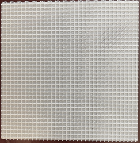
Fig. 4(a) shows the bare 3D-printed inkwell base. The aperture is discretized into a uniform candidate lattice with pitch . Each candidate location is a square inkwell with a opening and depth , printed into a dielectric base of total thickness (approximately mm bottom floor plus mm wall layer). The well walls (i) confine conductive ink during deposition and (ii) enforce a repeatable metallized footprint across prototypes.
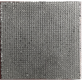
From a modeling perspective, the inkwell grid provides a fixed sampling scaffold for implementing the diagonal aperture interaction in the array-factor model. For spatial masking, a subset of wells is metallized to realize , thereby implementing the binary aperture described in Section III. For diffraction-order steering, entire columns are metallized with a uniform effective spacing to implement the periodic aperture described in Section IV. Metallization is implemented by filling selected inkwells with a commercial water-based conductive paint [27]. Fig. 4(b) shows the resulting all-ON configuration, where all wells are metallized. Since this paper targets azimuthal beam shaping, the designed 1-D pattern along the -axis is replicated across the -axis (constant vertical pitch), producing a striped 2-D aperture.
| Parameter | Value / Description |
|---|---|
| Aperture size | mm (square), centered at |
| Candidate grid (scaffold) | wells ( locations) |
| Center-to-center pitch | mm in and ( at GHz) |
| Inkwell opening (front) | mm square |
| Inkwell depth | mm (ink reservoir) |
| Base thickness | mm total |
| (0.4 mm bottom dielectric floor + 0.4 mm wall layer) | |
| Stencil thickness | mm |
| Stencil aperture | mm square (slightly smaller than wells) |
| Substrate material | 3D-printed dielectric (PLA/PETG) |
| Metallization | SilexCore conductive paint [27] deposited into wells (stencil-guided for masks) |
| Ground plane | Continuous copper tape/sheet on rear face (high reflectivity at 60 GHz) |
V-B Copper-Foil Backing as a Passive Ground Plane
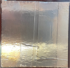
All prototypes use a continuous copper-foil tape layer on the rear side of the printed base to form a conductive ground plane (Fig. 4(c)). This backing is critical at GHz as it provides a high-conductivity termination that increases reflection efficiency and ensures that the front-side pattern (modulated by ON/OFF metallization or periodic activation) perturbs a strong reflected field.
V-C Stencil Layer for Repeatable Binary Metallization
For spatial-masking prototypes, we fabricate a matching 3D-printed stencil that enforces the designed ON/OFF pattern during conductive-ink deposition. The stencil (thickness ) contains square openings of (slightly smaller than the well openings) to reduce edge bleeding and improve pattern fidelity. The stencil is closed everywhere except at intended ON locations, so that the designed binary sequence is mapped into a repeatable metallization pattern. Fig. 5 shows representative CAD/STL renderings of the inkwell base and a corresponding stencil for a design case.
V-D Prototype Classes and Fabrication Workflow
Using the common printing-and-deposition workflow, we fabricate three prototype classes which correspond to the designs analyzed in Sections III and IV. Each prototype is realized by (i) 3D-printing the inkwell base (and, when applicable, a matching stencil), (ii) applying a continuous copper ground plane to the rear face, and (iii) depositing conductive paint into the selected inkwells. For mask-coded designs, the stencil confines deposition to the intended ON locations to improve pattern fidelity and repeatability.
The all-ON reference reflector in Fig. 4(b) metallizes all wells and serves as a baseline specular/reference response for measurement validation. For fixed-aperture 1-bit spatial masking, the distance remains fixed at and beam control is achieved by metallizing a subset of wells according to the designed binary mask. For diffraction-order steering, beam (lobe) placement is achieved by metallizing columns with a uniform effective spacing , with each active column replicated across rows to form a periodic 2-D pattern.
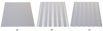
Fig. 6 shows fabricated prototypes for two representative steering configurations, and , comparing spatial-mask and diffraction-order realizations on the same inkwell platform. These prototypes are used in Section VII to validate the proposed beam-control methods through GHz azimuthal sweeps.
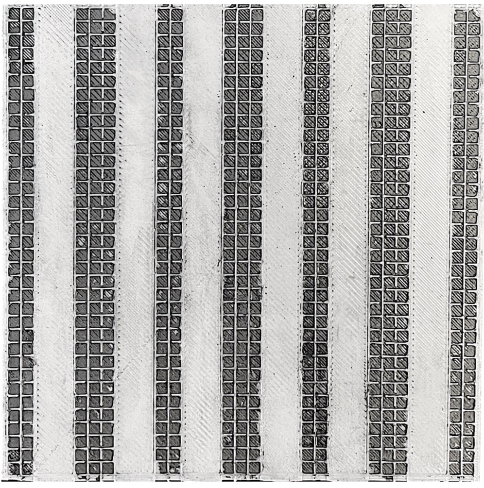
(a) Mask,
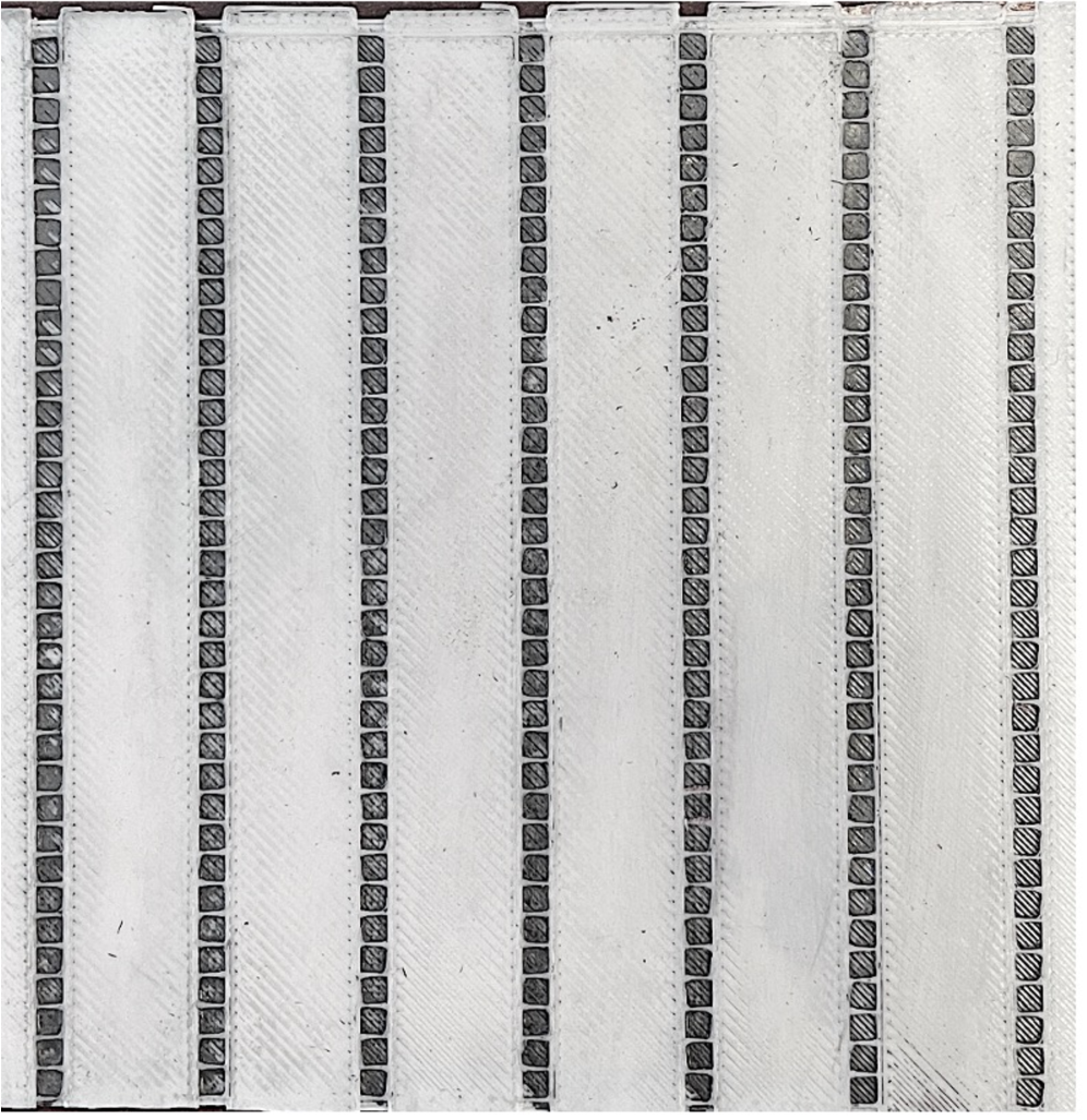
(b) Diffraction-order,
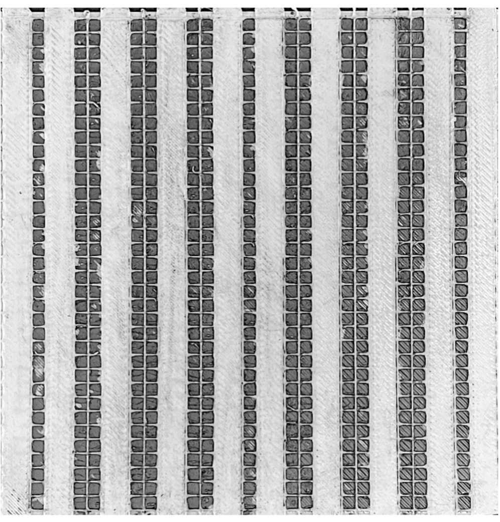
(c) Mask,
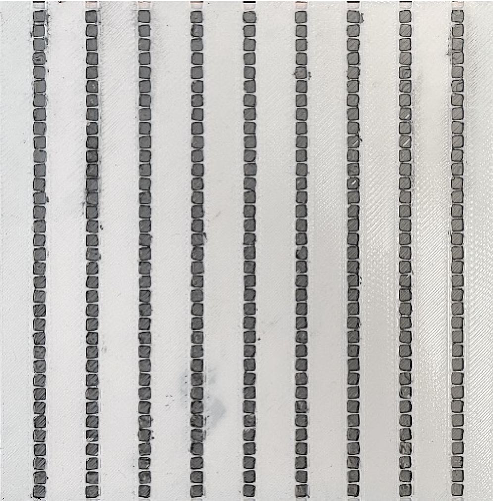
(d) Diffraction-order,
VI Performance Criteria and Evaluation Metrics
This section defines the metrics used to evaluate the fully passive, fabrication-coded reflectors. The proposed apertures are designed to synthesize deterministic non-specular departure lobes toward intended user directions. We quantify (i) target-direction power delivery and (ii) system-level impact under reflector-side operational-power constraints.
VI-A Angular Pattern Metrics
For a fixed incidence angle , the theoretical angular power pattern is
| (29) |
where denotes the departure angle in the reflection half-space. For the 1-D model with elements, we define the normalized gain as follows
| (30) |
and for a desired target departure angle , the target-direction power is
| (31) |
VI-B System-Level Mapping and Energy Efficiency
To connect target-direction performance to a system-level metric, we map the target-direction SNR to an achievable rate using the Shannon formula
| (32) |
where is the communication bandwidth. In the theoretical comparisons, can be interpreted as scaling with the target-direction gain in (31). Energy efficiency is then computed as [12, 11, 28]
| (33) |
where is the radiated transmit power, is the fixed radio/baseband power excluding , and is the surface-side operational power required by the reflecting structure. Energy efficiency is a key deployment metric because it captures delivered throughput per unit total power and explicitly accounts for surface-side overhead that impacts long-term operation in static installations. Combining (32) and (33) yields
which shows that increases with target-direction SNR through and decreases with total power consumption, particularly the surface-side overhead in powered RIS architectures. For the proposed passive desings, no biasing or control circuitry is required after installation, and thus during operation.
VII Results and Discussion
This section reports theoretical and experimental results for the proposed fully passive, fabrication-coded reflectors. Section VII-A characterizes 1-bit ON/OFF masking and diffraction-order steering, with bipolar () and ideal continuous-phase reflectors included as reference baselines. Section VII-B then presents 60 GHz OTA measurements and discusses agreement with theory and deployment implications.
VII-A Theoretical Results
Unless otherwise stated, theory is evaluated at 60 GHz ( mm) using a 1-D array-factor model with and . We report .
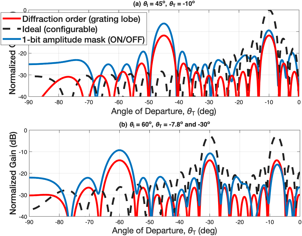
VII-A1 Single-target synthesis: ,
Fig. 7 compares the normalized gain for the all-ON aperture, the proposed ON/OFF mask, the bipolar () mask, and an ideal continuous-phase reflector. The all-ON aperture exhibits a dominant specular lobe at and weak non-specular response. In contrast, the ON/OFF mask forms a deterministic non-specular lobe toward by selecting lattice locations via the cosine-threshold rule.
The non-specular target response of ON/OFF masking exhibits a dB loss relative to the ideal continuous-phase upper bound, consistent with Lemma 2, which lower-bounds the maximum achievable normalized target-lobe gain by (i.e., dB). This loss is fundamentally due to amplitude-only control where an ideal surface can phase-align all contributions at the target. ON/OFF masking can only retain or suppress elements and cannot re-phase unfavorable contributions. At the specular direction, the ON/OFF pattern incurs a smaller loss (approximately dB) because the all-ON aperture is already phase-aligned and applying a non-specular mask primarily reduces the effective aperture through thinning and redistributes energy into other angles. In particular, Lemma 1 predicts an asymptotic activation ratio near , contributing an order-of- dB reduction, with the remaining loss attributable to the non-uniform spatial weighting introduced to form the non-specular lobe. The bipolar () mask allows sign reversals and therefore more closely approximates the ideal coherent sum at the target, yielding an dB loss, consistent with 1-bit phase quantization trends reported in [29].

VII-A2 Diffraction-order steering (unconstrained aperture)
Diffraction-order steering forms a non-specular lobe by enforcing a uniform effective period so that a chosen diffraction order satisfies the grating condition for the desired departure angle (Section IV). Fig. 8 illustrates at 60 GHz with mm, where all elements are active on the periodic lattice. With this choice of , a strong diffraction order is placed at while the zeroth-order (specular) response at is retained, as expected for a uniform-amplitude periodic aperture.
Because all elements participate coherently for the selected order, the target-lobe peak can approach the ideal continuous-phase upper bound in the unconstrained-aperture setting shown in Fig. 8. This gain advantage, however, is achieved by increasing the inter-element spacing from the dense scaffold spacing ( mm ) to mm, which expands the physical aperture when is held fixed. The increased aperture length leads to narrower angular features (sharper main lobes and nulls) which can make alignment more sensitive in practice.

VII-A3 Multi-target synthesis: ,
Fig. 9 considers a two-target design obtained by complex superposition of the desired phase ramps followed by binary thresholding as in (12)–(13). The ON/OFF mask produces two deterministic non-specular lobes at and while retaining a residual specular component at , which is expected under amplitude-only control. The bipolar () mask, by allowing sign reversals, more closely tracks the ideal continuous-phase reference and yields higher per-target coherence.
In the ideal continuous-phase case, the reflected energy is intentionally split across two directions, and therefore the peak gain at each target is reduced relative to the single-target setting. The ON/OFF and bipolar curves exhibit the same trend, with per-target peaks reduced by power sharing and by the 1-bit constraint. Notably, the characteristic loss behavior observed in the single-target case is preserved. When compared to the ideal continuous-phase reference, the ON/OFF masking exhibits non-specular penalty relative to ideal continuous-phase control that is consistent with the bound in Lemma 2, while the specular component experiences a lowerl reduction due to thinning and energy redistribution (as discussed for Fig. 7).
Fig. 10 shows a diffraction-order multi-lobe example where a larger effective period ( mm) produces multiple visible diffraction orders alongside the zeroth-order (specular) lobe. With held fixed, increasing expands the physical aperture and yields narrower angular profiles which can raise the peak levels at certain directions. This apparent gain improvement relative to ideal continuous-phase control , however, is primarily a consequence of the increased aperture size rather than an intrinsic advantage of periodic steering under fixed-footprint constraints.


VII-A4 Aperture-matched comparison
Diffraction-order designs can exhibit high target-lobe peaks in the unconstrained setting since selecting a larger period increases the physical aperture when is held fixed. To enable a fair “apples-to-apples” comparison, Fig. 11 evaluates Diffraction-order and dense ON/OFF masking under a fixed physical footprint. In this aperture-matched setting, increasing does not enlarge the reflector; instead, it reduces the number of active cells or elements that fit within the fixed length, thereby lowering the coherent gain available to the desired diffraction order.
As shown in Fig. 11(a), for the single-target case , the dense ON/OFF mask on the maintains a larger effective number of contributing cells and therefore sustains stronger target response than the aperture-matched Diffraction-order design. Fig. 11(b) shows the same trend in the multi-target setting where periodic steering becomes less efficient when the period increase forces a sparser effective aperture. This reduces coherent accumulation at each intended non-specular direction. These results indicate that, under fixed-size deployment constraints, dense ON/OFF masking is typically preferable. In contrast, Diffraction-order is attractive when aperture expansion is permissible due to its higher peak gains.
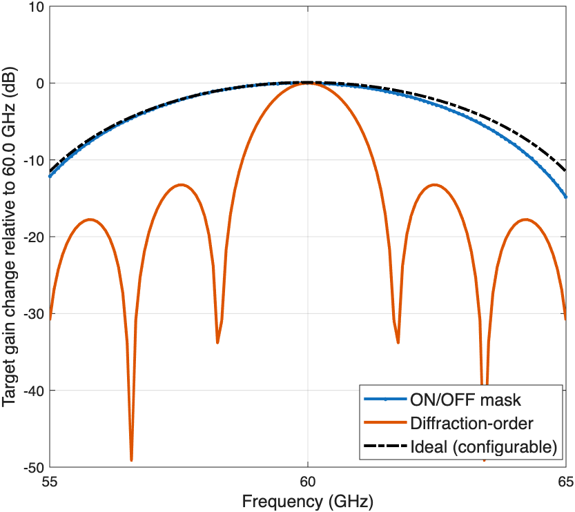
VII-A5 Target-direction gain variation across frequency.
Fig. 12 plots the target-direction gain change relative to the 60 GHz design point, , for three fixed-geometry reflectors (ON/OFF mask, diffraction-order, and ideal continuous-phase). For all schemes, the physical reflector (mask/period) is held constant while the carrier is swept from 55–65 GHz, so any degradation is due to wideband mismatch. The phase progression across the aperture scales with , and the design that is phase-aligned at becomes progressively misaligned as moves away from .
The ideal configurable baseline exhibits the smallest gain loss across the band, showing a smooth, approximately symmetric roll-off about 60 GHz. The proposed ON/OFF mask follows the ideal trend closely, with only a modest additional loss toward the band edges. This indicates that the binary amplitude gating is relatively robust to moderate fractional bandwidth. Although the mask is designed at 60 GHz, its effective aperture still retains significant coherent addition toward the target over the entire 55–65 GHz range.
In contrast, the diffraction-order (periodic) design shows severe frequency sensitivity, with deep notches reaching tens of decibels below the 60 GHz reference at certain frequencies. This behavior is inherent to periodic/grating-lobe steering where the target beam is produced by satisfying a wavelength-dependent diffraction condition, . When changes while the physical period is fixed, the designed order shifts away from causing abrupt target-gain losses These results highlight that diffraction-order steering can provide strong steering at the design frequency with very simple fabrication, but it is substantially less robust in wideband operation than the dense ON/OFF mask and the ideal continuous-phase upper bound.
VII-A6 Energy-efficiency implication under surface-power overhead
Fig. 13 illustrates the impact of surface-side operational power on energy efficiency at the target direction . Using the definitions in Section VI-B, we evaluate EE under a fixed radio-side power budget and vary only the surface-side term . The achievable rate is obtained from the target-direction SNR using (32). The example parameters used to generate the curves are given in the figure caption (e.g., GHz and baseline dB). For each reflector design, the target-direction is scaled according to its relative target gain, so that the resulting curves capture the joint effect of reflector-induced SNR improvement and added surface-side power.
Since the proposed reflectors are fully passive, and their EE curves remain essentially constant. In contrast, powered RIS baselines exhibit a monotonic EE reduction as increases, because controller/driver overhead and state-dependent unit-cell power increase the denominator of (33) without providing a commensurate increase in . This behavior is consistent with measurement-backed RIS power decompositions in which the controller term alone can be several watts (e.g., W [12, 11]). Overall, Fig. 13 highlights that eliminating surface-side operational power allows target-direction beam gains to translate more directly into higher bits/Joule, which is particularly relevant for static indoor installations.

| AoA | AoD | Scheme | (dB) | (dB) | (dB) |
| Passive (all-ON; specular) | |||||
| Metal plate (baseline) | |||||
| Proposed ON/OFF (1-bit amplitude) | |||||
| Diffraction-order (grating-lobe) | |||||
| Passive (all-ON; specular) | |||||
| Metal plate (baseline) | |||||
| Proposed ON/OFF (1-bit amplitude) | |||||
| Diffraction-order (grating-lobe) | |||||
| Passive (all-ON; specular) | |||||
| Metal plate (baseline) | |||||
| Proposed ON/OFF (1-bit amplitude) | |||||
| Diffraction-order (grating-lobe) | |||||
| Passive (all-ON; specular) | |||||
| Metal plate (baseline) | |||||
| Proposed ON/OFF (1-bit amplitude) | |||||
| Diffraction-order (grating-lobe) | |||||
| Passive (all-ON; specular) | |||||
| Metal plate (baseline) | |||||
| Proposed ON/OFF (1-bit amplitude) | |||||
| Diffraction-order (grating-lobe) |
VII-B Experimental Setup and OTA Results
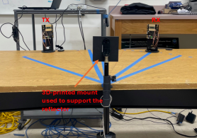
VII-B1 Experimental setup and processing
OTA measurements are performed at 60 GHz using two Sivers EVK02001 transceiver kits on a constant-radius arc (0.9m) centered on the reflector. The transmitter is fixed at azimuth AoA , while the receiver is swept in azimuth to measure the scattered response versus AoD . Two reference scans are collected: mount-only (background) and all-ON (reference reflector). Background-subtracted power is computed as
and target-direction results are reported using
VII-B2 OTA results and discussion
We evaluate both single-beam and multi-beam passive designs. The single-beam case uses with target , while the multi-beam case uses with targets . In addition to the fabricated all-ON inkwell reflector, we include a smooth copper plate as a baseline reference to verify that the all-ON metallization provides comparable specular behavior and to enable a consistent conductor baseline for comparison.
Table II reports the background-subtracted response , the enhancement over the passive all-ON baseline , and the normalized gain . The metric measures the target-direction level relative to the maximum background-subtracted response of the passive all-ON scan (specular lobe), and thus indicates how far a given angle lies below the strongest all-ON direction. In contrast, directly quantifies the gain improvement achieved by a given design over the passive all-ON reflector at the same .
The measurements confirm that the fabricated all-ON reflector behaves similarly to a solid conductor. At the specular directions, the copper-plate and all-ON responses are nearly identical, with only a small difference (about dB), indicating that the inkwell metallization with the copper backing provides a high-reflectivity baseline prior to applying any ON/OFF mask. Consistent with specular-dominated scattering under uniform weighting, the passive all-ON response is weak at non-specular targets. For , the direction is more than 20 dB below the all-ON peak in terms of , demonstrating that an unshaped passive surface does not effectively redirect energy.
Applying ON/OFF masking and diffraction-order synthesis redistributes energy away from the specular direction and toward the intended targets. This redistribution is visible as reduced specular response (negative at the specular angle) together with large positive enhancement at target angles. For the single-beam case , the ON/OFF reflector provides a strong target enhancement ( dB) and the diffraction-order design provides a comparable but slightly smaller improvement ( dB) under the fixed-footprint constraint. These trends are consistent with the theoretical aperture-matched plots in Fig. 11, where dense ON/OFF masking is favored when the physical aperture is fixed. At the specular angle, both ON/OFF and diffraction-order incur a penalty relative to all-ON because the designs intentionally suppress or reweight a portion of the aperture. For ON/OFF this is fundamentally tied to thinning (approximately activation ratio as shown in Lemma 1).
For the multi-beam case (), the ON/OFF and diffraction-order designs produce substantial enhancement at both target angles ( and ), confirming successful deterministic non-specular beam formation in a fully passive implementation. At the specular direction (), both designs exhibit reduced response relative to all-ON, which is expected since energy is redirected toward the non-specular targets. We note here that the measured magnitude of these specular losses and target gains do not always match the worst-case theoretical bounds relative to an ideal continuous-phase surface, however, the experimentally relevant comparison is against the passive all-ON baseline, for which the measured target enhancements are consistently large. This is becuase the theory in Section VII-A is developed using a 1-D azimuthal array-factor abstraction, whereas the fabricated reflector is a 2-D lattice and the measurements are azimuth cuts of a 2-D scattering pattern. Additional aperture extent in the orthogonal dimension, elevation-dependent weighting, and indoor multipath can affect absolute levels and partially explain deviations from idealized 1-D predictions. Nevertheless, the measured ranking and trends across all-ON, ON/OFF, and DGO designs remain consistent with theory as shown in Fig. 12.
VIII Conclusion
This paper presented a theory-to-hardware framework for fully passive millimeter-wave beam shaping using in-lab fabricated, low-cost 3D-printed reflectors. Beam patterns are fabrication-coded on a fixed dense lattice using binary masks or periodic activation and realized via stencil-assisted conductive deposition on a copper-backed “inkwell” substrate. Two complementary passive mechanisms were developed and validated: fixed-aperture 1-bit ON/OFF spatial masking for non-specular steering and multi-beam synthesis, and diffraction-order (grating-lobe) steering via uniform period selection to place a chosen diffraction order at a desired departure angle.
The experimental results highlight an important tradeoff between these mechanisms. Diffraction-order steering is attractive due to its simplicity, but it typically produces narrower angular features and is therefore more sensitive to alignment errors and geometric mismatch. It is also more susceptible to beam squint under wideband operation because the grating condition is wavelength dependent. This reduces coherence at a fixed target direction as frequency or angle deviates from the design point. In contrast, dense ON/OFF masking operates on a fixed footprint and provides greater flexibility for shaping the angular response (including multi-beam patterns), with improved robustness to practical deployment tolerances.
Future work will extend the framework to full two-dimensional aperture synthesis for joint azimuth–elevation beam control and polarization engineering, and will investigate semi-static control mechanisms (e.g., swappable masks or mechanically indexed patterns) suitable for indoor millimeter-wave electromagnetic environment shaping. We will also study pattern improvements through fabrication and material optimization, including the impact of cell width (effective metallized aperture per cell), metallization thickness/uniformity, and deposition methods to reduce ohmic loss and improve coherent reradiation efficiency.
Appendix A Proof of Lemma 1: Asymptotic Activation Ratio of the Cosine-Threshold Mask
Recall that the element locations are and define the phase associated with the th element as
Substituting into yields the affine phase progression
| (34) |
where Hence, the phase increment is constant and satisfies . The cosine-threshold activation rule is given by
Since is -periodic, the activation depends only on . Introduce the normalized phase variable
Under the condition (equivalently ), the sequence is uniformly distributed on by Weyl’s equidistribution theorem. Equivalently, is uniformly distributed on the unit circle, with providing a convenient normalized representation. To relate equidistribution to the cosine-threshold activation rule, define the function
This choice of directly encodes the ON/OFF masking rule in normalized phase coordinates, since
By the defining consequence of equidistribution, for any Riemann-integrable function ,
Applying this result to the above choice of yields
| (35) |
The limiting integral corresponds to the fraction of the unit interval for which the cosine-threshold condition is satisfied. Define the set
Since the integral of an indicator function equals the Lebesgue measure of its support, we obtain
Therefore,
This establishes the asymptotic activation ratio and completes the proof of Lemma 1.
Appendix B Proof of Lemma 2
Consider a complex number , its magnitude can be written as Applying this to in (18) and exchanging the two maximizations gives
| (36) |
For fixed , the inner maximization is separable in and, since , we have where . Define the normalized objective so that (36) can be written compactly as
| (37) |
A distribution-free lower bound can be obtained by noting that the maximum of a function is no smaller than its average, hence
| (38) |
Interchanging the finite sum and the integral (by linearity) and then applying the change of variables gives
| (39) |
where the first equality follows from linearity and the change of variables is used in the second step. Since is -periodic, each term in the sum is identical and independent of . Averaging therefore removes element-dependent phase offsets. Note the integrand equals on (mod ) and is zero elsewhere; therefore Combining with (39) yields Using (37) and (38) we conclude
which proves the amplitude bound (20). Squaring both sides yields , completing the proof.
References
- [1] C.-X. Wang et al., “On the road to 6G: Visions, requirements, key technologies and testbeds,” IEEE Commun. Surveys Tuts., vol. 25, no. 2, pp. 905–974, Feb. 2023.
- [2] Q. Xue et al., “A survey of beam management for mmWave and THz communications towards 6G,” IEEE Commun. Surveys Tuts., vol. 26, no. 3, pp. 1520–1559, 3rd Quart. 2024.
- [3] M. Ahmed et al., “A survey on RIS advances in terahertz communications: Emerging paradigms and research frontiers,” IEEE Access, vol. 12, pp. 173867–173901, 2024.
- [4] Y. Xing and T. S. Rappaport, “Millimeter wave and sub-terahertz spatial statistical channel modeling for wireless communications,” IEEE J. Sel. Areas Commun., vol. 39, no. 6, pp. 1506–1524, Jun. 2021.
- [5] R. W. Heath et al., “An overview of signal processing techniques for millimeter wave MIMO systems,” IEEE J. Sel. Topics Signal Process., vol. 10, no. 3, pp. 436–453, Apr. 2016.
- [6] A. Taha, M. Alrabeiah, and A. Alkhateeb, “Enabling large intelligent surfaces with compressive sensing and deep learning,” IEEE Access, vol. 9, pp. 44304–44321, 2021.
- [7] C. Huang, A. Zappone, G. C. Alexandropoulos, M. Debbah, and C. Yuen, “Reconfigurable intelligent surfaces for energy efficiency in wireless communication,” IEEE Trans. Wireless Commun., vol. 18, no. 8, pp. 4157–4170, Aug. 2019.
- [8] M. A. ElMossallamy et al., “Reconfigurable intelligent surfaces for wireless communications: Principles, challenges, and opportunities,” IEEE Trans. Cogn. Commun. Netw., vol. 6, no. 3, pp. 990–1012, Sep. 2020.
- [9] S. V. Hum and J. Perruisseau-Carrier, “Reconfigurable reflectarrays and array lenses for dynamic antenna beam control: A review,” IEEE Trans. Antennas Propag., vol. 62, no. 1, pp. 183–198, Jan. 2014.
- [10] Y. Liu et al., “Reconfigurable intelligent surfaces: Principles and opportunities,” IEEE Commun. Surveys Tuts., vol. 23, no. 3, pp. 1546–1577, 3rd Quart. 2021.
- [11] J. Wang, W. Tang, S. Jin, X. Li, and M. Matthaiou, “Static power consumption modeling and measurement of reconfigurable intelligent surfaces,” in Proc. 31st Eur. Signal Process. Conf. (EUSIPCO), 2023, pp. 890–894.
- [12] J. Wang, W. Tang, J. C. Liang, L. Zhang, J. Y. Dai, X. Li, S. Jin, Q. Cheng, and T. J. Cui, “Reconfigurable intelligent surface: Power consumption modeling and practical measurement validation,” IEEE Trans. Commun., vol. 72, no. 9, pp. 5720–5734, Sep. 2024.
- [13] J.-B. Gros, V. Popov, M. A. Odit, V. Lenets, and G. Lerosey, “A reconfigurable intelligent surface at mmWave based on a binary phase tunable metasurface,” IEEE Open J. Commun. Soc., vol. 2, pp. 1055–1064, 2021.
- [14] H. Kamoda, T. Iwasaki, J. Tsumochi, T. Kuki, and O. Hashimoto, “60-GHz electronically reconfigurable large reflectarray using single-bit phase shifters,” IEEE Trans. Antennas Propag., vol. 59, no. 7, pp. 2524–2531, Jul. 2011.
- [15] A. S. Shekhawat, B. G. Kashyap, R. W. Raldiris Torres, F. Shan, and G. C. Trichopoulos, “A millimeter-wave single-bit reconfigurable intelligent surface with high-resolution beam-steering and suppressed quantization lobe,” IEEE Open J. Antennas Propag., vol. 6, no. 1, pp. 311–325, Feb. 2025.
- [16] A. H. Naqvi, D. A. Pham, S. I. H. Shah, and S. Lim, “1-bit transmission-type digital programmable coding metasurface with multi-functional beam-shaping capability for Ka-band applications,” Micromachines, vol. 14, no. 6, Art. no. 1250, Jun. 2023.
- [17] T. Huang, W. Fu, D. Lu, Y. Pan, M. Wang, and Y. Yan, “Wideband 1-bit reconfigurable transmission metasurface unit cell design in Ka-band with polarization hold and conversion,” Scientific Reports, vol. 13, Art. no. 20076, Nov. 2023.
- [18] P. Li, T. Yang, J. Ren, and Y. Yin, “Design of 1-bit reconfigurable reflectarray based on miniaturized reconfigurable unit,” in Proc. IEEE Int. Microwave Workshop Series on Antennas and Propagation (IMWS-AMP), Chongqing, China, Nov. 2021, pp. 370–372.
- [19] W. Khawaja, O. Ozdemir, Y. Yapici, F. Erden, and I. Guvenc, “Coverage enhancement for NLoS mmWave links using passive reflectors,” IEEE Open J. Commun. Soc., vol. 1, pp. 263–281, 2020.
- [20] Z. Peng et al., “An effective coverage scheme with passive-reflectors for urban millimeter-wave communication,” IEEE Antennas Wireless Propag. Lett., vol. 15, pp. 398–401, 2016.
- [21] A. P. Ganesh, W. Khawaja, O. Ozdemir, I. Guvenc, H. Nomoto, and Y. Ide, “Propagation measurements and coverage analysis for mmWave and sub-THz frequency bands with transparent reflectors,” in Proc. IEEE 97th Veh. Technol. Conf. (VTC2023-Spring), Jun. 2023, pp. 1–6.
- [22] O. Ibrahim, R. S. S. Bandari, and M. E. Eltayeb, “LiDAR-aided millimeter-wave range extension using a passive mirror reflector,” in Proc. IEEE 22nd Consum. Commun. Netw. Conf. (CCNC), Jan. 2025, pp. 1–4.
- [23] S. Häger, M. Danger, K. Heimann, Y. Gümüs, S. Böcker, and C. Wietfeld, “Custom design and experimental evaluation of passive reflectors for mmWave private networks,” in Proc. IEEE 30th Int. Symp. Local and Metropolitan Area Netw. (LANMAN), Boston, MA, USA, 2024, pp. 52–57.
- [24] K. Qian et al., “MilliMirror: 3D printed reflecting surface for millimeter-wave coverage expansion,” in Proc. 28th Annu. Int. Conf. Mobile Comput. Netw. (MobiCom), Oct. 2022, pp. 15–28.
- [25] K. Qian and X. Zhang, “Demo: Fully passive 3D printed reflecting surface for millimeter-wave coverage expansion,” in Proc. 20th Annu. Int. Conf. Mobile Syst., Appl. Serv. (MobiSys), Jun. 2022, pp. 1–2.
- [26] H. L. Van Trees, Optimum Array Processing (Detection, Estimation, and Modulation Theory, Part IV). Wiley-Interscience, 2002.
- [27] SilexCore Conductive Paint, product page. [Online]. Available: https://www.amazon.com/dp/B0DJTYJD7V
- [28] M. Rihan, A. Zappone, S. Buzzi, G. Fodor, and M. Debbah, “Passive versus active reconfigurable intelligent surfaces for integrated sensing and communication: Challenges and opportunities,” IEEE Network, May/Jun. 2024.
- [29] Q. Wu and R. Zhang, “Beamforming optimization for wireless network aided by intelligent reflecting surface with discrete phase shifts,” IEEE Trans. Commun., vol. 68, no. 3, pp. 1838–1851, Mar. 2020.