Advancing Minimally Invasive Precision Surgery in Open Cavities with Robotic Flexible Endoscopy
Abstract
Flexible robots hold great promise for enhancing minimally invasive surgery (MIS) by providing superior dexterity, precise control, and safe tissue interaction. Yet, translating these advantages into endoscopic interventions within open cavities remains challenging. The lack of anatomical constraints and the inherent flexibility of such devices complicate their control, while the limited field of view of endoscopes restricts situational awareness. We present a robotic platform designed to overcome these challenges and demonstrate its potential in fetoscopic laser coagulation—a complex MIS procedure typically performed only by highly experienced surgeons. Our system combines a magnetically actuated flexible endoscope with teleoperated and semi-autonomous navigation capabilities for performing targeted laser ablations. To enhance surgical awareness, the platform reconstructs real-time mosaics of the endoscopic scene, providing an extended and continuous visual context. The ability of this system to address the key limitations of MIS in open spaces is validated in vivo in an ovine model.
1 Introduction
Flexible endoscopy robots have the potential to transform minimally invasive surgery (MIS) by offering enhanced dexterity, deformability, and intrinsic safety compared to conventional rigid instruments Dupont et al. (2021); da Veiga et al. (2020) (see Figure 1A). However, their inherent compliance and high-dimensional configuration space pose significant challenges for modeling, controlling, and sensing Russo et al. (2023); Nazari et al. (2022); da Veiga et al. (2020). To date, most advances have concentrated on luminal environments, where flexible devices navigate in narrow and tortuous environments and are constrained by the lumen’s wall Prado et al. (2024); Brumfiel et al. (2025); Greenidge et al. (2025); Dreyfus et al. (2024); Martin et al. (2020). Although flexible endoscopy robotic platforms targeting open cavities such as a pregnant uterus, the stomach, or the urinary bladder are promising, they have so far remained in the early research stages with few preclinical results focused on device dexterity rather than targeting entire surgeries Mao et al. (2024); Ahmad et al. (2023); da Veiga et al. (2020). The nature of these environments makes navigation and trajectory planning challenging due to the absence of anatomical constraints to naturally guide and stabilize flexible devices. Additional challenges of these single-port procedures include small instrument diameters that limit the amount of integrated sensing and a lack of overview of the surgical scene due to the limited field of view of endoscopic cameras, which are navigated close to the tissue surface Bano and Stoyanov (2024); Phan et al. (2020). The latter poses a significant mental load on surgeons, who must memorize the environment during the procedure for localization and navigation, as well as identification and characterization of areas of interest. To address this issue, the generation of 3D reconstructions or panorama images, also called mosaics, has been proposed. Recent advances in computer vision and machine learning have led to promising results with clinical endoscopic camera images of those challenging low-texture environments Bano and Stoyanov (2024); Li et al. (2023); Phan et al. (2020); Widya et al. (2021), where traditional methods fail. However, most of these methods focus on offline processing, and none have been translated to the clinic to date.

A challenging endoscopic MIS in open cavities that would benefit from flexible surgical robots and the generation of endoscopic image mosaics is fetoscopic laser coagulation (FLC). It is the gold standard treatment for twin-to-twin transfusion syndrome (TTTS), a life-threatening disease of twin fetuses in the womb. TTTS is characterized by an imbalanced blood flow between twins who share the same placenta and affects 10-15% of such twin pregnancies Van Der Veeken et al. (2019); Bamberg and Hecher (2022). Even when performed by highly trained and experienced surgeons in high-volume centers, double-twin survival rates of only 70% have been reported, and 10% of the surviving children exhibit long-term neurodevelopmental impairments Bamberg and Hecher (2019).
The purpose of FLC is to stop the blood flow between the twins. The surgeon inserts an endoscope through a trocar into the uterus, scans the placental surface to identify all vascular anastomoses that connect the twins’ circulations, and ablates these vessels using a surgical laser Van Der Veeken et al. (2019); Pandya et al. (2020). Operating on anterior placentas located towards the abdomen of the mother is particularly challenging due to their limited accessibility with the current curved rigid endoscopes Bouchghoul et al. (2025); Bamberg and Hecher (2019). Limited manipulability results in a tangential view of the placental surface, making visualization, identification, and ablation of anastomoses difficult or even impossible Cruz-Martínez et al. (2023). As a consequence, incomplete separation of the circulations may occur, increasing the risk of recurrence of the condition after surgery Van Der Veeken et al. (2019).
In a clinical study conducted by Cruz-Martinez et al., the authors reported the benefits of using a flexible video endoscope in addition to conventional instruments for FLC Cruz-Martínez et al. (2023). Although this approach led to better visibility of the placental surface and enabled coagulation of anastomoses that would not be possible otherwise, the device was challenging to operate due to its additional degrees of freedom and required two trained operators, rather than the single fetal surgeon needed for the conventional treatment.
Ahmad et al. developed a hand-held flexible endoscope with a pneumatically actuated distal tip deflection mechanism for FLC Ahmad et al. (2023). They demonstrated improved access, visualization, and ablation performance over conventional endoscopes during a user study. They remain the only group to date to have evaluated their active endoscope in vivo, with an emphasis on showing enhanced access for ablation in an ovine model. Although their work highlights the advantages of having an endoscope with a flexible distal tip, the saturation of the endoscopic camera sensor during lasering prevented them from demonstrating a reliable vessel ablation. Their system also did not leverage the active pneumatic actuation to provide automated robotic assistance or closed-loop control, which has the potential to significantly reduce the complexity of device manipulation. Hernansanz et al. demonstrated robotic assistance capabilities in vitro Hernansanz et al. . Their platform allows the user to save and navigate back to points of interest, but is limited to easy-to-access posterior placentas as their platform consists of a straight endoscope mounted on a robot arm.
Our group previously demonstrated the potential of a magnetically guided flexible endoscope for FLC Lussi et al. (2022). This preliminary work demonstrated in vitro and ex vivo navigation capabilities and ablation of vessels in ex vivo human placentas. However, controlling the direction of the external magnetic field with a haptic controller rather than the direction of motion of the endoscopic images proved too counterintuitive for future clinical use. Autonomous navigation capabilities were shown for short distances toward a target visible in the endoscopic view and limited to ex vivo settings. More recently, we demonstrated how endoscopic image mosaics enable autonomous navigation in open cavities, which has the potential to significantly improve the outcome and reduce the complexity of procedures such as FLC Mattille et al. (2024).
This work introduces a flexible surgical platform that addresses the key challenges of MIS in open cavities. Its benefits and efficacy are demonstrated in realistic preclinical conditions for the treatment of complex cases of TTTS (see Figure 1B). Our platform is able to access and ablate vessels precisely in any placental location and can generate mosaics of endoscopic images in real time. It also offers intuitive manual steering as well as supervised automated navigation over both short and long ranges, providing robotic assistance relevant to the different phases of the FLC procedure (see Figure 1C-F). Our approach overcomes the negative effects of hand tremors on lasering performance and safety and significantly improves the accuracy and precision to reach and ablate targets compared to a state-of-the-art conventional instruments. Our robotic platform also significantly reduces the physical strain and frustration imposed on its users compared to conventional FLC. These findings are supported by user studies conducted with both an experienced clinician and novices, and by in vitro, and ex vivo experiments, as well as in vivo experiments at human scale in a living ovine model. This work presents the first in vivo demonstration of a robotic fetal surgery platform featuring assisted navigation capabilities and visualization during ablation in the context of FLC, marking an important step toward the clinical translation of the robotic treatment of TTTS.
2 Results
2.1 Robotic platform design
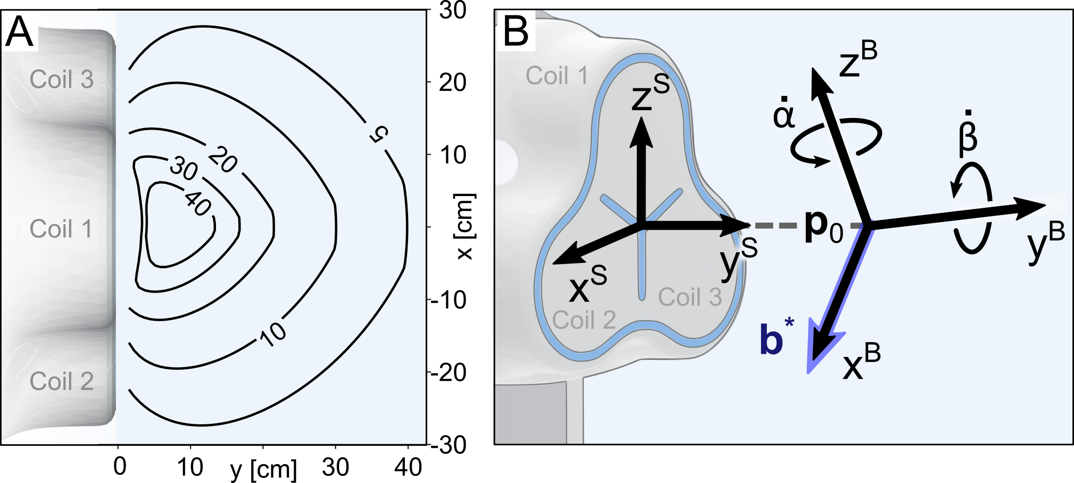
Our robotic platform comprises a flexible endoscope with a magnetically actuated distal tip, which is steered by external magnetic fields generated by a preclinical electromagnetic navigation system Gervasoni et al. (2024), and the insertion depth is controlled by a mechanical advancer unit (see Figure 2D). The electromagnetic navigation system (eMNS) enables control of the endoscope’s orientation (see Figure 1B). Endoscopic images can be stitched in real time to generate image mosaics (see Figure 1D), which further enhance visualization and exploration capabilities of the anatomical environment based on automated scanning motion as proposed in Mattille et al. (2024). Navigation can be performed using three strategies that cover the range of tasks encountered during FLC: (1) manual navigation, in which the user controls the motion of the endoscopic image via a joystick, (2) short-range automated navigation, which steers the tip to targets visible within the endoscopic view, and (3) long-range automated navigation to targets outside the current view, selected on a previously generated image mosaic (see Figure 1C-F).
2.2 Robotic endoscope design
We developed a robotic endoscope with an outer diameter (OD) of 3.2 mm (see Figure 2A). It is compatible with 10 French (Fr) trocars commonly used in FLC, where larger trocars have been associated with less favorable clinical outcomes Bouchghoul et al. (2025); van der Schot et al. (2024). The device features a transparent tip that integrates optical fibers for illumination, a CMOS camera (OVM6946, OmniVision), and a working channel for a laser fiber (OD of 500 m or less) as illustrated in Figure 2C. The distal section comprises a series of stacked magnets and precision-engineered steel ball joints (see Figure 2B), designed using the open-source software toolbox introduced in Mesot et al. , to allow large bending angles and precise magnetic navigation. For stability in the magnetic field, this distal section is followed by a stainless steel rod (OD of 3 mm, ID of 1.7 mm). A waterproof handle houses the camera board and provides access to the working channel. The section between the tip and the handle is surrounded by a soft Pebax jacket.

2.3 Workspace characterization
The robotic endoscope workspace was characterized by subjecting the device to a magnetic field of 25 mT generated by the eMNS, with a 200 core laser fiber inserted into the device. By sweeping over the magnetic field directions, the endoscope’s tip bent in various directions. Figure 2B shows the tracked endoscope’s tip positions in space during this experiment. A maximum bending angle of 173 was achieved for the endoscope in the upward configuration.
2.4 Accessible uterine locations characterization
To characterize the ability of our robotic endoscope to ablate vessels located on an anteriorly located placenta during FLC, we determined the best angle between the endoscope tip axis and the uterine surface for all accessible locations on a uterus model at 26 weeks of gestation (see Figure 2F). An angle of is considered optimal for visualization and vessel ablation Akkermans et al. (2017b).
The analysis was performed for an insertion point on the lateral uterine wall. The results were compared to a curved, rigid endoscope (11508AAK, Karl Strotz, Germany) designed for anteriorly located placentas. The conventional endoscope was simulated using a constant curvature model, and the reachable poses of the robotic endoscope were interpolated from its experimental characterization (see Figure 2E). Instrument poses were simulated for a range of insertion angles and insertion lengths using a parameter sweep. At each point on the uterine wall surface, the optimal value of between the tip and the local tangent of the uterine wall was determined among all poses where the instrument tip pointed to this position. Any pose where the distance between the instrument tip and fell outside the 3 to 10 mm range was discarded.
Results show that the robotic endoscope can access more locations on the uterus surface (see Figure 2F), and with better ablation angles across the anterior uterine wall compared to the conventional device. The robotic endoscope achieved angles greater than 45 at 91% of the locations on the anterior uterine surface, compared to 73% for the conventional endoscope. For angles exceeding 70, the robotic and conventional endoscopes covered 89% and 33% of the anterior surface, respectively. On the left lateral uterine wall, the conventional device exhibited progressively smaller angles as the target points approached the insertion site until the area became unreachable. In contrast, the robotic endoscope maintained high ablation angles across the surface, apart from the immediate vicinity of the insertion point.
2.5 Image-based magnetic field control

The control of the endoscope’s motion is solely based on the endoscopic image feedback. It consists of changing the external magnetic field to bend its tip, and using image-based visual servoing to achieve a desired velocity in the endoscopic image, or reach a 2D target point selected in that image or in a previously generated image mosaic. The proposed navigation methods do not require any additional embedded sensors or tracking devices. The 2D velocity of a point defined in the endoscopic image is linearly mapped to the instantaneous rotation of the magnetic field vector (see Figure S1) using the image Jacobian matrix which linearly maps to . The matrix is initially estimated with a calibration process and is then updated over time using the Broyden method Wu et al. (2015) to guarantee the validity of the mapping as the endoscope moves.
The choice of a point and of its desired velocity depends on the selected navigation strategy. For manual navigation, is defined as the desired motion of the image center. Its direction coincides with the direction of the joystick operated by the user, and its magnitude is set to a fixed value. For short-range automated navigation, is defined as a target location selected in the endoscopic image, and its desired velocity is updated using a PID control law so that the target moves to a reference position , which is typically in the center of the image. For long-range automated navigation, the target location is chosen in a previously generated image mosaic outside of the current endoscopic image. First, the endoscope is moved with a magnetic field estimated to correspond to the target location. Once the target is in proximity of the reference position in the endoscopic image, short-range automated navigation is used for the remaining distance.
2.6 In vitro characterization of the imaged-based control
This image-based control was first evaluated in vitro by navigating the robotic endoscope for desired image motions of the image center with stepwise and continuous direction changes at a constant speed (see Figure 3). The directional component of the motion is more important to the user than the magnitude to make navigation feel intuitive. The closer the desired and actual directions are, the more intuitive the navigation strategy feels. The endoscope was inserted horizontally from the side with its tip pointing forward and upward (see Figure 3E-F), which are the most challenging configurations to control given the destabilization effect of gravity. This simulates interventions on lateral and anterior placentas during FLC.
The trajectories of the image center over time can be estimated by integrating its speed (see Figure 3A-B), and they approximate a square and a circle, respectively, as expected from the given inputs. The stepwise direction change is the most demanding as the change in motion direction is instantaneously applied (see Figure 3C). In this case, we observed an overshoot with a median peak error of and an overall median error of 2.2. Continuous direction changes show smoother motion and only minor deviations from the desired direction (see Figure 3D), with a median error of .
The importance of updating the image Jacobian matrix is illustrated in Figure S2, which shows a significantly lower performance in following the desired motion when the Jacobian is kept constant after an initial calibration. This results in a significant deviation from the square and circular trajectories obtained with the update. This update requires a robust estimate of the motion of the image center over time. The estimated local image motion and the ground truth are shown in SM with a mean and standard deviation of pixel/s of the absolute error over time.
2.7 In vivo navigation in an ovine model
We demonstrated the feasibility of our navigation strategies under preclinical conditions in vivo in an ovine model. Ovine models are well-established models in fetal and reproductive surgery due to their physiological similarities in neonatal development and placenta with humans Lussier et al. (2025); Kabagambe et al. (2018). Conducting such experiments is critical for validating the system’s performance, as this is the closest available model we have to mimic the complex physiological environment encountered in humans.


An experienced fetal surgeon first steered the endoscope with a joystick using the manual navigation method. They successfully navigated along a vessel on the uterine wall, simulating a real task performed in FLC (see Movie S1). The results show a close match between the desired motion from the joystick input and the estimated motion over time (see Figure 4A-D), with a median and median absolute deviation of the angle error of throughout the trajectory. The successive endoscopic images were stitched into an image mosaic (see Figure 4E), which shows the surgeon could follow the desired vessel with only a limited deviation between the center line of the vessel and the center of the image.
Using short-range automated navigation, six targets selected within the endoscopic view were reached with the center of the image as the reference position and within a threshold of two pixels (see Figure S8). Figure 5A-D illustrates the target trajectory at different keyframes, and the evolution of the error over time for the second target (see Figure S8B, Movie S2). The six targets were reached within s following an initial calibration. Travel distances were pixels and fall times were s. The delay time of the system response time was s.
The long-range automated navigation to targets selected outside the current endoscopic image and within an image mosaic was also validated under in vivo conditions (see Figure 5E-I, Movie S3, Figure S9-S10). The mosaic was first built by automatically navigating the endoscope along a spiral trajectory within the mosaic reference frame. The images were stitched together to form a mosaic image in real time (see Figure S6). The completed mosaic served as an interactive user interface, allowing for the successful automated navigation to five manually selected target locations throughout the mosaic. Each target was reached with an error threshold of two pixels with a mean duration of (see Movie S3, Figure S10).
2.8 Ex vivo vessel ablation study on human placenta
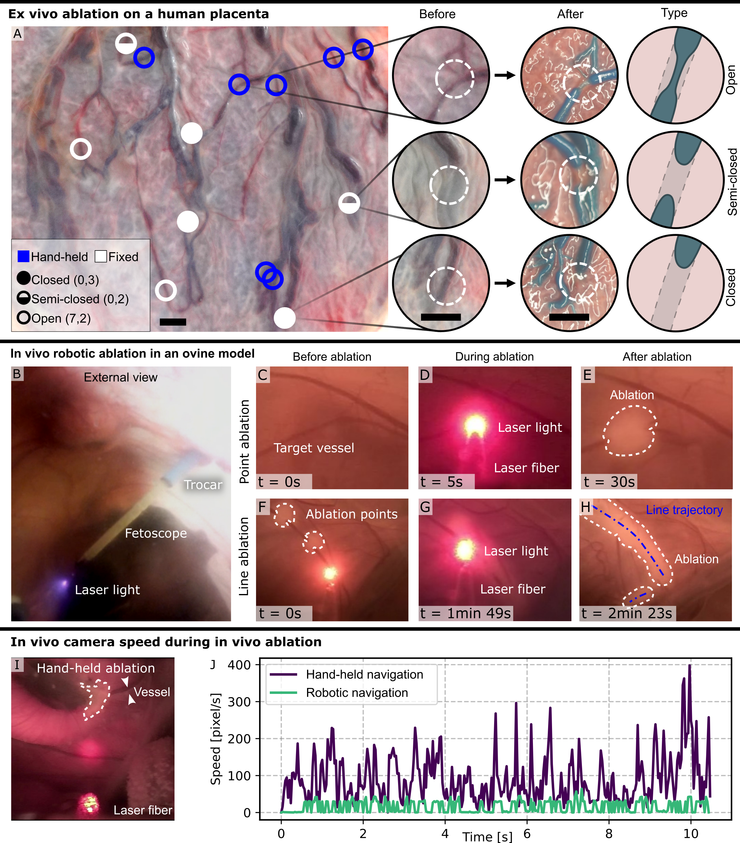
The impact of hand tremors on the energy required for vessel ablation was investigated on an ex vivo human placenta. Vessel ablations were compared using a hand-held replica of a conventional endoscope, with the same laser fiber fixed in place and with similar duration, laser power, and distance to the vessel to simulate the robotic endoscope, which can be kept still in a constant magnetic field. To evaluate whether the ablated vessels were closed, a colored dye was injected through the umbilical cord after ablation using the protocol introduced in Lopriore et al. (2011). Figure 6A and S12 show the results of the experiment. The ablated vessels were classified into three different types: Fully closed if the ablation was complete (i.e. no penetration of the color dye passed the ablation point), semi-closed if no color was visible at the ablation site but the dye still penetrated further down along the vessel, and open if the dye was still visible at the ablation site.
At the selected laser duration and laser power, none of the vessels could be fully ablated with the hand-held endoscope, while out of the 7 vessels targeted with the fixed fiber, 3 could be fully closed and 2 semi-closed. These results indicate that the robotic endoscope, which is able to maintain stable positioning over the vessel target, can successfully ablate vessels with reduced laser energy compared to a conventional hand-held endoscope.
2.9 In vivo vessel ablation in an ovine model
To demonstrate the feasibility of vessel ablation in clinical settings, a fetal surgeon ablated vessels in vivo with the robotic endoscope in an ovine model. They performed both point and line ablations on the placental vessels (see Figure 6B-H and Movies S4-5). This simulated the Solomon technique, which is a state-of-the-art maneuver in FLC procedures consisting of connecting previously coagulated anastomoses with an ablation line Van Der Veeken et al. (2019). The results also show that vessels were still visible during ablation (see Figure 6D and G), which is important for precise and safe ablations. Here, this is made possible by the integration of a filter on top of the camera sensor (see Figure 2C) to avoid the saturation of the camera sensor due to reflected laser light during lasering.
To investigate the influence of a hand tremor in vivo, the endoscope was held manually instead of being fixed in the advancer, and the magnetic field was kept constant to stabilize the flexible distal tip. The surgeon held the endoscope as steady as possible while ablating another vessel (see Figure 6I-J, Movie S6). Figure 6J shows the speed of the center of the image over time for both point ablations. The mean speed and standard deviation was lower for the robotic navigation with pixel/s compared to pixel/s for the hand-held approach. This accounts for the noticeable difference between the spread of the ablation energy, which is qualitatively illustrated in Figure 6F and I, showing a more localized lasering mark on vessels ablated under magnetic guidance.
2.10 Usability study
To demonstrate the usability of the robotic platform, we conducted a user study to assess and compare the performance of assisted manual control of the robotic endoscope with a replica of a hand-held conventional endoscope to perform two tasks commonly performed during FLC: (1) ablation of targets at different locations in the uterus to simulate coagulation of individual anastomoses, and (2) ablation along trajectories simulating the Solomon technique Van Der Veeken et al. (2019). The study was carried out using an augmented reality setup (see Figure S14), where subjects received visual feedback consisting of endoscopic images augmented with a game environment to overlay virtual targets. Eleven participants completed each task three times with both instruments, and completed a NASA-TLX questionnaire for each run to score perceived workloads in terms of mental, physical, and temporal demand, as well as performance, effort, and frustration. For both tasks, robotic endoscope navigation was performed with image-based manual navigation, while conventional endoscope was operated by hand without additional assistance.

In Task 1, the participants were asked to ablate 12 virtual targets on a simulated anterior placenta as quickly and accurately as possible (see Figure 7A-B and Movie S7). This task alternated between navigation phases to go from the current target to the next, and ablation phases where the participant used a foot pedal to simulate the laser trigger (see Figure 7B). The accuracy and precision were significantly better for our robotic endoscope compared to the conventional endoscope (see Figure 7C), with median errors in all runs, targets, and subjects of 14022 compared to 621361 for the accuracy during the ablation of targets (p = 0.001, W= 0.0, paired Wilcoxon signed-rank test). The time to navigate between targets was significantly longer for the robotic endoscope, with a median of 20 s seconds, compared to 8.5 s for the commercial replica (p = 0.001, W= 0.0). No significant differences were observed between the devices for the duration of the ablation phase.
In Task 2, the participants were asked to follow a continuous ablation trajectory in the endoscopic image (see Figure 7E and Movie S8). Only the sections of the trajectory where the participant pressed the foot pedal for ablation were considered for evaluation (see Figure 7E). The accuracy and precision were significantly better for our robotic endoscope compared to the commercial endoscope (see Figure 7F), with weighted median error of 302187 for the robotic endoscope compared to 451187 for the commercial replica. The completion time was significantly shorter for the commercial replica with a median value over runs and subjects of 104 s compared to 162 s.
NASA-TLX results analysis shows that the use of the robotic endoscope led to a significant reduction in physical demand, effort, and frustration for both tasks compared to the hand-held endoscope according to a paired Wilcoxon signed rank test (see Figure 7D and G). In addition, it also led to a significant reduction in mental demand in Task 2.
3 Discussion
Our endoscopic robotic platform addresses the key challenges of MIS in open organs with flexible robotic devices. We propose image-based navigation methods in open space with various levels of autonomy which do not rely on modeling the complex robot kinematics or on the integration of additional sensors for precise localization. Our robotic endoscope is able to create an overview of the surgical scene through real-time mosaicking of endoscopic images, and show the potential of surgical robots for precise and safe vessel ablation by eliminating the negative impact of hand tremors. The efficacy of our approach was demonstrated in clinically realistic conditions in vivo and on a human scale in an ovine model.
This work focuses on addressing the current limitations encountered during FLC, a challenging minimally invasive fetal surgery in the uterus to treat TTTS. It should only be performed by highly trained and experienced surgeons, as twin survival rates have been strongly correlated with the annual case load of hospitals Akkermans et al. (2015). These considerations make this procedure a relevant target for our platform, with clear expected benefits from its use in clinical settings. Facilitating surgery through robotic assistance has the potential to improve outcomes in low-volume centers, as surgeons with less training can perform it at a higher level of skill, thus reducing geographical discrepancies Dupont and Degirmenci (2025).
We show that the access to anteriorly located placentas during fetal surgery can be improved with our platform by using a flexible robotic endoscope instead of a conventional rigid instrument (see Figure 2). Flexible devices can provide a more dexterous and potentially safer navigation during MIS Dupont et al. (2021), including for the treatment of TTTS Rodrigue and Kim (2024); Bamberg and Hecher (2019); Spruijt et al. (2020). In this case, they allow for improved visualization of the placental vasculature and better ablation angles, which is a main factor in the efficacy of vessel ablation Akkermans et al. (2017b). Access to previously inaccessible vessels leads to a more complete separation of the twins’ circulatory systems, thereby avoiding recurrence of the disease Cruz-Martínez et al. (2023); Bouchghoul et al. (2025) and the risk of neurological damage Stirnemann et al. (2018).
Real-time mosaicking of endoscopic images during MIS in open organs provides maps of the anatomical environment Bano and Stoyanov (2024). In this study, we generate these mosaics in real time during autonomous exploration motions and demonstrate how mosaics can serve as a user interface to efficiently access locations outside of the current camera image under supervised autonomy (see Figure 5E-I and S9). This contribution is relevant to FLC where the identification and ablation of all shared vessels between the twins are key Peeters et al. (2015). The surgeon must currently memorize the vasculature as the endoscope must be held close to the placental surface for good visualization Peeters et al. (2015); Pandya et al. (2020). In this case, mosaicking and supervised autonomous navigation can lower the mental load of the surgeon and facilitate navigation back to previously inspected vessels.
Our platform offers intuitive navigation strategies with various levels of robotic assistance, which have the potential to reduce inter- and intra-surgeon variability by standardizing surgical techniques, minimizing human factors such as stress or fatigue, and allowing less experienced surgeons to handle more complex cases by facilitating the procedure Han et al. (2022). This in turn would allow trainees to focus less on steering the device and more on the critical factors of the procedure Fagogenis et al. (2019). Autonomy can provide more consistency and precision in surgeries, improving efficiency, safety, and potentially reducing complication rates Schmidgall et al. (2025). Although task autonomy provides many benefits, it does not eliminate the need for manual navigation. When autonomous behavior is used in clinics, it is under the supervision or in collaboration with surgeons Lee et al. (2024); Dupont and Degirmenci (2025), who must be able to take over at any time in the event of unforeseen conditions or emergencies. In these situations, having an intuitive control over the tool is crucial. Therefore, we also introduce a manual navigation strategy that allows the surgeon to freely follow and ablate individual vessels (see Figure 4 and 6B-H). Together, the four navigation strategies implemented in this work cover the main surgeons’ needs during an FLC procedure. These include the possibility of manually following and ablate individual vessels, autonomously exploring an area, and navigating back to specific targets within or outside of the current endoscopic view for point ablations (see Figure 4 and 5). Beyond their relevance to FLC, these strategies lend themselves to advancing navigation capabilities in MIS using flexible instruments.
Our experiments show that robotic control significantly improves accuracy and precision during endoscopic laser ablation procedures (see Figure 6 and 7C and F) as it eliminates hand tremors, leading to a reduced laser exposure time and energy. Although physiological movements are also expected to hinder ablation quality and safety, they remained limited during in vivo experiments and could be manually corrected. In the case of FLC, the preservation of healthy placental tissue is critical, as placental damage has been associated with serious complications, including preterm premature membrane rupture (PPROM) Akkermans et al. (2017a) and preterm birth before 32 weeks of gestation De Zoysa et al. (2020). Reducing laser energy while enhancing its efficacy may, therefore, lead to better perinatal outcomes Spruijt et al. (2020). Furthermore, reducing invasiveness by having the endoscope fixed at the insertion site while moving its tip can further contribute to decreasing the rate of PPROM after FLC by limiting the friction and shear forces of the instrument port with the fetal membranes Amberg et al. (2021); Beck et al. (2012).
Our user study showed an improvement in both usability and performance using a robotic approach over a manual approach. Users manipulating the robotic endoscope reported a significant reduction in physical demand, effort, and frustration compared to the conventional tool (see Figure 7D and G). Statistically significant reduction in mental load was only obtained for the trajectory ablation (see Figure 7G). This is attributed to difficulties in estimating the depth required for the target during the first task, which was a challenge for many subjects. Reduction of the mental and physical load on physicians and improvement of ergonomics are among the motivations and expected benefits of incorporating surgical robots into clinical practice Han et al. (2022); Wee et al. (2020). Our results indicate that even with limited training, the robotic platform is intuitive and easy to handle. Future work includes the development of distance detection and the integration of depth information into automation to further improve usability. Although this study was simulated for tasks encountered in FLC specifically, its findings emphasize the promise of our platform to facilitate MIS and reduce the mental and physical burden on physicians in endoscopic procedures in general.
The navigation strategies we propose have the potential to be readily adapted to various actuation mechanisms beyond magnetics because they are exclusively image-based. Visual servoing and recent progress in surgical computer vision have shown promise for the control of rigid and flexible continuum robots in challenging surgical scenes Nazari et al. (2022); Azizian et al. (2014, 2015). Our methods are model-free, so they can be readily applied to various devices, including flexible instruments, which are generally more challenging to control. They also do not require the integration of additional sensors to infer the position and shape of the device, which contributes to keeping the dimensions of the instruments as small as possible. In addition, image-based processing is robust to different surgical environments, as the approaches were designed for low-texture environments rather than focusing on the placental vasculature.
The feasibility and safety of our platform was demonstrated in vivo. By advancing the technical readiness of this approach for FLC, this work takes a significant step toward its clinical translation for fetal surgery. The assistive functions provided by the platform were designed to address critical and mentally demanding aspects of the procedure while maintaining the engagement and oversight of the surgeon. The combination of endoscopic image mosaics with autonomous navigation capabilities exhibits potential benefits for MIS in other anatomical regions such as the stomach and bladder, where endoscopic image mosaicking and 3D reconstructions have already been proposed to improve visualization and localization of instruments during cancer screenings Lurie et al. (2017); Phan et al. (2020); Widya et al. (2021).
4 Materials and Methods
4.1 Endoscope design
The endoscope exhibits the functionalities of regular endoscopes and was tested with two commercial laser fibers, which have been evaluated for FLC ex vivo (OD of 500 m, KLS Martin) and in human (OD of 300 m, Giga Laser, China) Lussi et al. (2022); Cruz-Martínez et al. (2023). Our endoscopes contain a small CMOS camera (OVM6946, OmniVision), optical fibers (optical grade plastic, OD of 250 m, Edmund Optics, Germany) for illumination and a channel for a laser fiber (polyimide, OD of 0.69 mm, ID of 0.64 mm, ZEUS Inc., USA). A filter is placed over the camera to avoid saturation during lasering due to reflections on the tissue (2.1 x 1.6 mm size, Colored Glass Heat Absorbing Shortpass Filter KG5, SCHOTT). The tip of the endoscope is 3D-printed and transparent (PX 521HT Polyurethane). An array of 9 NdFeB magnets is placed behind the tip (OD of 3mm, segments with ID of 1.9 and 1.7 lengths of 2 and 4 mm, X-Magnet, China) followed by a flexible section consisting of an array of soft-magnetic 440 stainless steel ball joints with magnets in between (OD of 3mm, ID of 1.7mm, full joint length of 4.2 mm). Magnetic ball joints provide flexibility and stability in magnetic fields of 10-23 mT Mesot et al. . For stability, the proximal ball joint is welded to a nonmagnetic 316 stainless steel hypodermic tube (OD of 2.8 mm, ID of 1.7 mm, McMaster Carr, USA). A flexible endoscopic insertion tube section consisting of a spring with a USP class VI biocompatible polyurethane jacket (EDC, USA) connects the stainless steel tube to the casing of the camera board, acting as a stress relief connector at the mechanical junction. The casing is waterproof and contains connectors for illumination and the camera and contains an insertion point for the channel of the laser fiber. It is mounted on a FISSO surgical arm (see Figure S7A). The outer layer between the endoscope tip and the casing consists of a soft Pebax jacket (Durometer = 35 D, Nordson Medical, USA).
4.2 Endoscope workspace characterization
The endoscope was mounted at 150 mm in front of the eMNS coils, which generated a magnetic field of 25 mT (see Figure S1A). The magnetic field was rotated in a sweeping motion in different planes, while the tip of the endoscope was tracked with an optical tracking system (OTS, Vicon Motion Systems Ltd). Unstable configurations of the endoscope under this rotating field described in Tunay (2004); Peyron et al. (2018) were removed from the data in post-processing. Transitions from stable to unstable configurations were detected by comparing the measured tip acceleration to a pre-defined threshold. The poses depicted in Figure 2E were filtered with a Savitzky-Golay filter.
4.3 Accessible uterus location simulation
The accessible locations of the uterus and the ablation angles shown in Figure 2F were determined in two steps. First, all reachable poses in free space were determined for each device for a given insertion pose. For the robotic endoscope the poses were interpolated based on the measurements shown in Figure 2E and for the conventional endoscope they were calculated over a constant curvature model with a radius of 210 mm. The different insertion poses were then calculated by sweeping over the insertion angles and and the insertion depth . Secondly, the poses were converted to rays simulating the laser light during ablation. The intersections with the triangles of a mesh uterus model at 26 weeks gestation were found over ray casting. Rays which length between their source and their intersection with the mesh were outside of the range mm were discarded. The angle between the remaining rays and their tangents at the intersection point were then calculated. Figure 2F shows the highest per triangle, which was filtered with a low-pass filter. In clinical practice, the range of motion may be limited by anatomical constraints, such as maternal hip bones or the pelvic floor, which were neglected in our simulations.
4.4 Electromagnetic navigation
When the robotic endoscope is placed in an external magnetic field a magnetic torque is exerted on each magnet comprised in the tool
| (1) |
where is the magnetic dipole moment of each magnet that causes its distal section to bend. To control the endoscope tip with a magnetic field at a position in space, the current in each of the three electromagnets in our eMNS Gervasoni et al. (2024) is calculated over the linear mapping:
| (2) |
where is the Moore-Penrose pseudoinverse of the actuation matrix, which is found by calibration Petruska et al. (2017).
4.5 Image-based control
The proposed navigation strategies control the 2D motion of a point in the endoscopic image through eye-in-hand image-based visual servoing. To generate this motion, the orientation of magnetic field vector is updated at each time step with an intrinsic rotation around the reference frame attached to such that . It is first rotated around its -axis with and then around its -axis with (see Figure S1B). The desired 2D motion of a point in the endoscopic image is then mapped to the instantaneous rotation of the magnetic field vector as follows
| (3) |
The image Jacobian matrix is initially estimated with a calibration process. It is then updated at each time step using the Broyden method Wu et al. (2015) with
| (4) |
where and are the estimates of at the time steps and , is the update rate, is the magnetic field rotation between the time steps and , and is the estimated motion of the point per time step and must not be noisy Bonkovi et al. (2006). This estimated motion is defined as
| (5) |
describing the change in the image coordinates of between the steps and (right subscript) in the frame of the current image (left subscript). At each new step, the desired magnetic field change is computed to achieve the desired motion as
| (6) |
where and assuming that the estimated Jacobian has full rank.
The estimated motion in the camera image originates either from the motion of the endoscope or from physiological motion. The latter is negligible compared to the endoscope’s movements. To ensure that is only updated when the endoscope is moving, the estimated speed has to exceed a predefined threshold.
4.6 Manual control
We introduce a manual navigation strategy that allows the user to steer the robotic endoscope image using a joystick. The user controls the motion of the image center of coordinates in the frame of the current image. The desired motion has a fixed speed and its direction matches the direction of the joystick controlled by the user. The estimated motion is defined as the difference between , and the feature at the center of the previous image projected onto the current frame (see equation 5) that is obtained here as
| (7) |
where is a scale factor and is the homography projecting onto and calculated based on the optical flow of the pixels according to Alabi et al. (2022). To avoid inaccurate matches between pixels in the images due to reflections or insufficient illumination, the images are thresholded and masked before estimating . The images were converted to grayscale and pixel values above a predefined threshold were masked to remove reflections, the influence of the guide light or laser light, and below a second threshold in case the illumination was insufficient in some areas.
4.7 Short-range automated control
For the short-range automated navigation the user selects a target location in the current endoscopic image and the endoscope automatically moves it to the reference position in the image (typically located in the center of the image). The desired motion is defined as the output of a proportional–integral–derivative (PID) controller over the error between the reference position and the target position as follows
| (8) |
where the control parameters , and are found by empirical tuning. The estimated actual motion is defined as the difference in target locations in images and . The PID parameters of the controller were initially tuned in vitro to achieve a fast response and minimal overshoot, and the same parameters were applied during in vivo experiments without further adjustment.
4.8 Autonomous exploration motions
The endoscopic image mosaics generated during the in vivo experiment were obtained while the endoscope autonomously explored its environment following a spiral or grid trajectory in the mosaic frame (see Figure S6). The method proposed here improves on the one introduced in Mattille et al. (2024), which was only applicable to explore relatively small regions around the posterior orientation of the endoscope. The present work addresses this limitation by updating the image Jacobian matrix for a more accurate mapping over larger areas, as well as increased robustness in various endoscopic orientations (see Figure S2).
4.9 Long-range automated control
The long-range automated control guides the endoscope to targets selected in a previously generated image mosaic, which are typically outside of the endoscopic view. First, the magnetic field at the target location is estimated by interpolating previous field orientations, visual servoing is then used to navigate the remaining distance. We extended the visual servoing part from Mattille et al. (2024) to make it more robust to in vivo conditions. Instead of assuming that the target is visible in the endoscopic image at the magnetic field , we now only assume that contains enough common features with the previous image , from which the selected target on the mosaic originates, so it is possible to determine the homography between the two images.
The following additional steps were introduced: After the endoscope navigated to the magnetic field , the target is projected from the image , which is the endoscopic image from which the pixel of the target on the mosaic originates, to the frame “k” of the current endoscopic image . If the norm of the error between the reference position and the target position is larger than a threshold pixels, a waypoint is introduced. It is defined as the projection of the target on a circle of radius centered in (see Figure 5G)
| (9) |
The endoscope is then guided with short-range navigation towards . When the error is below the target proximity threshold of pixels the target is projected again from the mosaic image onto the current image and the endoscope is guided towards another waypoint or the final target (see Figure 5H-I).
4.10 In vitro navigation characterization
To characterize the performance of the image Jacobian update and the visual servoing in Figure 3 and Figure S2, the endoscope was mounted horizontally at 145 mm from the eMNS, which generated a magnetic field of 15 mT. The inputs consisted of stepwise direction changes with 90 steps of 18 s in duration, or of a continuous direction change over time with a rate change of 6.3 deg/s. The magnetic field magnitude was kept constant. For each input setting, 5 runs were performed from the same starting position for visual servoing while updating the image Jacobian matrix , and another 5 runs keeping it constant. Before each run, the matrix was calibrated at the starting position.
The ground truth signal of the velocity of the center of the image shown in Figure S4 was calculated based on the camera poses obtained over the localization of the plate with the visual fiducials Olson (2011); Wang and Olson (2016). The velocity is calculated over , where is the difference between the current image center and the projection of the previous image center on the current image frame and is the difference in time between the frames. The projection between the images and is calculated based on the camera poses.
4.11 Ex vivo ablations
The placenta used for ex vivo ablation (Figure 6A and S12) was placed in a saline solution to mimic the amniotic fluid (see Figure S11). The vessels were ablated by a trained user with a clinical Nd:Yag laser (My 60, KLS Martin, Austria) and with laser fibers with a core OD of 300 (KLS Martin, Austria), which were fixed in space or inserted in the replica of the conventional endoscope. To mimic the stability provided by the maternal body wall, the latter device was inserted through a ball joint, which was fixated in space. To ensure a constant distance of 2 mm between the vessels and the laser fiber, a placeholder was used for positioning prior to each ablation. The minimal required laser power and duration per vessel diameter were determined empirically over visual inspection of the ablations, and the same settings were subsequently used for all ablations of vessels with the same diameters. The completeness analysis of the ablations was performed visually using colored dye injected through the umbilical cord according to the protocol proposed in Lopriore et al. (2011), which is routinely performed for placenta analysis after birth of TTTS patients Bamberg and Hecher (2019); Spruijt et al. (2020). If a vessel is fully ablated, the colored dye is not able to penetrate the vessel further than the location of the ablation. The experiment was approved by the Ethics Committee of the District of Zürich, Switzerland under the number BASEC-Nr: 2023-00110, and written consent was obtained when the placenta was donated.
4.12 In vivo experiment
The experimental setup is depicted in Figure S7. Before the experiment, the endoscopic camera was calibrated in saline solution (Ri – Ac/Mal, Ringerfundin B. Braun) to mimic the properties of amniotic fluid. One pregnant ewe (black mountain sheep, 50 kg, 90-100 days of gestation, singleton pregnancy) was placed under general anesthesia and placed on a surgical table with the Navion system placed lateral to the operating table as close to the abdomen as possible. Throughout the procedure, a veterinarian team closely monitored the sheep, while the surgery itself was performed by two experienced fetal surgeons. A median laparotomy with uterine exteriorization was performed. A trocar (Cook Medical, US) was then placed anteriorly in the amniotic sac of the fetus at a distance of 135 mm from the Navion as the insertion point for the robotic endoscope. For visualization of the endoscope and the surgical environment a cannula (VersaOne, Medtronic, Ireland) was placed laterally to insert a custom-built rigid endoscope with a camera (OCHSA10, OmniVision) and illumination at its tip (see Figure S5. To increase the volume of the uterus and increase visibility in the amniotic fluid, warm saline solution (Ri – Ac/Mal, Ringerfundin B. Braun) was infused into the uterus. The robotic endoscope was then pushed through the trocar and navigation and ablation experiments were performed (shown in Figure 4-6 and Movies S1-6 and 9). No complications arose during the experiments. Subsequently, the fetus and the ewe were euthanized and the fetus was examined by an experienced veterinarian and it was confirmed that it was healthy and did not suffer any injuries due to the procedure. The animal study was approved by the local Committee for Animal Experimental Research (Cantonal Veterinary Office Zurich, Switzerland) under the license number ZH117/2023.
4.13 Usability study
The augmented reality setup for the usability study is depicted in Figure S14. Of the 11 participants in the usability study, no one had prior experience steering the robotic endoscope, five people had 0.5-5 years of experience in magnetic catheter and endoscope navigation with other devices and steering algorithms, and one fetal surgeon had with 25 years of experience in endoscopy. Each participant completed the user study in a single session using the same setup. Informed written consent was given after confirming eligibility.
Each task consisted of a training period, which was followed by three test runs, separated by short breaks and the completion of a NASA-TLX questionnaire. For the first task, the training and testing periods were 4 min and 11 min and for the second task they were 2 min and 5 min, respectively. The protocol was repeated for the second device. The order of the devices was alternated between the participants. The protocol is shown in Figure S13.
The ablation accuracy and precision of task 1 were calculated as the mean and standard deviation of the in-plane error per sample resulting in for the two metrics. For task 2, were calculated as the weighted median for the accuracy and weighted median absolute deviation between the actual and optimal trajectory for the precision. The median of each metric across runs was then calculated per target, giving . Finally, the median of across all targets provided a subject-specific value for each metric which are shown in Figure 7C and F. Only runs that did not timeout were considered, leading to the exclusion of two subjects for the first task.
4.13.1 Statistical analysis
The statistical significance in the results of the user study was obtained over a paired Wilcoxon signed-rank test. The degree of statistical significance is illustrated in the figures with star annotations, where one star corresponds to , two stars represent and three stars .
References
- Development and validation of a flexible fetoscope for fetoscopic laser coagulation. International Journal of Computer Assisted Radiology and Surgery 18 (9), pp. 1603–1611 (en). External Links: ISSN 1861-6429, Link, Document Cited by: §1, §1.
- What is the impact of placental tissue damage after laser surgery for twin-twin transfusion syndrome? A secondary analysis of the Solomon trial. Placenta 52, pp. 71–76. External Links: ISSN 0143-4004, Link, Document Cited by: §3.
- Twenty-Five Years of Fetoscopic Laser Coagulation in Twin-Twin Transfusion Syndrome: A Systematic Review. Fetal Diagnosis and Therapy 38 (4), pp. 241–253. Note: Publisher: S. Karger AG External Links: ISSN 1015-3837, Link, Document Cited by: §3.
- Impact of Laser Power and Firing Angle on Coagulation Efficiency in Laser Treatment for Twin-Twin Transfusion Syndrome: An ex vivo Placenta Study. Fetal Diagnosis and Therapy 42 (3), pp. 204–209. Note: Publisher: S. Karger AG External Links: ISSN 1015-3837, Link, Document Cited by: §2.4, §3.
- Robust fetoscopic mosaicking from deep learned flow fields. International Journal of Computer Assisted Radiology and Surgery 2022, pp. 1125–1134. Note: Publisher: Springer External Links: ISSN 1861-6429, Link, Document Cited by: §4.6.
- Why Do the Fetal Membranes Rupture Early after Fetoscopy? A Review. Fetal Diagnosis and Therapy 48 (7), pp. 493–503. External Links: ISSN 1015-3837, Link, Document Cited by: §3.
- Visual servoing in medical robotics: a survey. Part I: endoscopic and direct vision imaging – techniques and applications. The International Journal of Medical Robotics and Computer Assisted Surgery 10 (3), pp. 263–274 (en). Note: _eprint: https://onlinelibrary.wiley.com/doi/pdf/10.1002/rcs.1531 External Links: ISSN 1478-596X, Link, Document Cited by: §3.
- Visual servoing in medical robotics: a survey. Part II: tomographic imaging modalities – techniques and applications. The International Journal of Medical Robotics and Computer Assisted Surgery 11 (1), pp. 67–79 (en). Note: _eprint: https://onlinelibrary.wiley.com/doi/pdf/10.1002/rcs.1575 External Links: ISSN 1478-596X, Link, Document Cited by: §3.
- Update on twin-to-twin transfusion syndrome. Best Practice & Research Clinical Obstetrics & Gynaecology 58, pp. 55–65. External Links: ISSN 1521-6934, Link, Document Cited by: §1, §1, §3, §4.11.
- Twin-to-twin transfusion syndrome: Controversies in the diagnosis and management. Best Practice & Research Clinical Obstetrics & Gynaecology 84, pp. 143–154. External Links: ISSN 1521-6934, Link, Document Cited by: §1.
- Chapter 15 - Image mosaicking. In Medical Image Analysis, A. F. Frangi, J. L. Prince, and M. Sonka (Eds.), The MICCAI Society book Series, pp. 387–411. External Links: ISBN 978-0-12-813657-7, Link, Document Cited by: §1, §3.
- Preterm Prelabor Rupture of Membranes and Fetal Survival after Minimally Invasive Fetal Surgery: A Systematic Review of the Literature. Fetal Diagnosis and Therapy 31 (1), pp. 1–9. External Links: ISSN 1015-3837, Link, Document Cited by: §3.
- A new method for uncalibrated visual servoing. In 9th IEEE International Workshop on Advanced Motion Control, 2006., pp. 624–629. Note: ISSN: 1943-6580 External Links: Link, Document Cited by: §4.5.
- Management of twin‐to‐twin transfusion syndrome: update and current challenges. American Journal of Obstetrics & Gynecology MFM 7 (8), pp. 101714. External Links: ISSN 2589-9333, Link, Document Cited by: §1, §2.2, §3.
- A variable stiffness robotically steerable guidewire for endovascular interventions. npj Robotics 3 (1), pp. 21 (en). Note: Publisher: Nature Publishing Group External Links: ISSN 2731-4278, Link, Document Cited by: §1.
- Flexible Video Fetoscopy: Feasibility and Outcomes of a Novel Modality for Laser Therapy in Twin-to-Twin Transfusion Syndrome Presenting with Inaccessible Anterior Placenta. Fetal Diagnosis and Therapy 50 (2), pp. 106–114 (en). External Links: ISSN 1015-3837, 1421-9964, Link, Document Cited by: §1, §1, §3, §4.1.
- Challenges of continuum robots in clinical context: a review. Progress in Biomedical Engineering 2 (3), pp. 032003 (en). Note: Publisher: IOP Publishing External Links: ISSN 2516-1091, Link, Document Cited by: §1.
- Membrane Separation and Perinatal Outcomes after Laser Treatment for Twin-Twin Transfusion Syndrome. Fetal Diagnosis and Therapy 47 (4), pp. 307–314. External Links: ISSN 1015-3837, Link, Document Cited by: §3.
- Dexterous helical magnetic robot for improved endovascular access. Science Robotics 9 (87), pp. eadh0298. Note: Publisher: American Association for the Advancement of Science External Links: Link, Document Cited by: §1.
- The grand challenges of learning medical robot autonomy. Science Robotics 10 (104), pp. eadz8279. Note: Publisher: American Association for the Advancement of Science External Links: Link, Document Cited by: §3, §3.
- A decade retrospective of medical robotics research from 2010 to 2020. Science Robotics 6 (60), pp. eabi8017. Note: Publisher: American Association for the Advancement of Science External Links: Link, Document Cited by: §1, §3.
- Autonomous robotic intracardiac catheter navigation using haptic vision. Science Robotics 4 (29), pp. eaaw1977. Note: Publisher: American Association for the Advancement of Science External Links: Link, Document Cited by: §3.
- A Human-Scale Clinically Ready Electromagnetic Navigation System for Magnetically Responsive Biomaterials and Medical Devices. Advanced Materials 36 (31), pp. 2310701 (en). Note: _eprint: https://onlinelibrary.wiley.com/doi/pdf/10.1002/adma.202310701 External Links: ISSN 1521-4095, Link, Document Cited by: §2.1, §4.4.
- Harnessing the oloid shape in magnetically driven robots to enable high-resolution ultrasound imaging. Science Robotics 10 (100), pp. eadq4198. Note: Publisher: American Association for the Advancement of Science External Links: Link, Document Cited by: §1.
- A systematic review of robotic surgery: From supervised paradigms to fully autonomous robotic approaches. The International Journal of Medical Robotics and Computer Assisted Surgery 18 (2), pp. e2358 (en). Note: _eprint: https://onlinelibrary.wiley.com/doi/pdf/10.1002/rcs.2358 External Links: ISSN 1478-596X, Link, Document Cited by: §3, §3.
- [26] Robot Assisted Fetoscopic Laser Coagulation: Improvements in navigation, re-location and coagulation. External Links: Link Cited by: §1.
- Lessons from the Barn to the Operating Suite: A Comprehensive Review of Animal Models for Fetal Surgery. Annual Review of Animal Biosciences 6 (Volume 6, 2018), pp. 99–119 (en). Note: Publisher: Annual Reviews External Links: ISSN 2165-8102, 2165-8110, Link, Document Cited by: §2.7.
- Levels of autonomy in FDA-cleared surgical robots: a systematic review. npj Digital Medicine 7 (1), pp. 103 (en). Note: Publisher: Nature Publishing Group External Links: ISSN 2398-6352, Link, Document Cited by: §3.
- Robust endoscopic image mosaicking via fusion of multimodal estimation. Medical Image Analysis 84, pp. 102709. Note: Publisher: Elsevier External Links: ISSN 13618415, Link, Document Cited by: §1.
- Accurate and Simple Evaluation of Vascular Anastomoses in Monochorionic Placenta using Colored Dye. Journal of Visualized Experiments : JoVE 55, pp. 3208. External Links: ISSN 1940-087X, Link, Document Cited by: §2.8, §4.11, Analysis of vessel ablations on ex vivo human placenta.
- 3D reconstruction of cystoscopy videos for comprehensive bladder records. Biomedical Optics Express 8 (4), pp. 2106–2123. Note: Publisher: Optica Publishing Group External Links: ISSN 21567085, Link, Document Cited by: §3.
- Magnetically Guided Laser Surgery for the Treatment of Twin-to-Twin Transfusion Syndrome. Advanced Intelligent Systems 4 (11), pp. 2200182 (en). Note: _eprint: https://onlinelibrary.wiley.com/doi/pdf/10.1002/aisy.202200182 External Links: ISSN 2640-4567, Link, Document Cited by: §1, §4.1.
- Sheep Models in Translational Surgery. European Surgical Research 66 (1), pp. 39–45. External Links: ISSN 0014-312X, Link, Document Cited by: §2.7.
- Magnetic steering continuum robot for transluminal procedures with programmable shape and functionalities. Nature Communications 15 (1), pp. 3759 (en). Note: Publisher: Nature Publishing Group External Links: ISSN 2041-1723, Link, Document Cited by: §1.
- Enabling the future of colonoscopy with intelligent and autonomous magnetic manipulation. Nature Machine Intelligence 2 (10), pp. 595–606. Note: Publisher: Nature Publishing Group External Links: ISSN 25225839, Link, Document Cited by: §1.
- Autonomous Magnetic Navigation in Endoscopic Image Mosaics. Advanced Science 11 (19), pp. 2400980. Note: Publisher: John Wiley & Sons, Ltd External Links: ISSN 2198-3844, Link, Document Cited by: §1, §2.1, §4.8, §4.9.
- [37] Parametric Design of Continuum Robots Using Interlocking Ball Joints. Advanced Intelligent Systems n/a (n/a), pp. 2500180 (en). Note: _eprint: https://advanced.onlinelibrary.wiley.com/doi/pdf/10.1002/aisy.202500180 External Links: ISSN 2640-4567, Link, Document Cited by: §2.2, §4.1.
- Visual servoing of continuum robots: Methods, challenges, and prospects. The International Journal of Medical Robotics and Computer Assisted Surgery 18 (3), pp. e2384 (en). Note: _eprint: https://onlinelibrary.wiley.com/doi/pdf/10.1002/rcs.2384 External Links: ISSN 1478-596X, Link, Document Cited by: §1, §3.
- AprilTag: A robust and flexible visual fiducial system. 2011 IEEE International Conference on Robotics and Automation, pp. 3400–3407. Note: ISBN: 9781612843865 External Links: ISSN 10504729, Link, Document Cited by: §4.10, Localization of the endoscopic camera for ground truth measurements.
- Current Practice and Protocols: Endoscopic Laser Therapy for Twin-Twin Transfusion Syndrome. Maternal-Fetal Medicine 2 (1), pp. 34–47. Note: Publisher: Ovid Technologies (Wolters Kluwer Health) External Links: ISSN 26415895, Link, Document Cited by: §1, §3.
- Identification of essential steps in laser procedure for twin–twin transfusion syndrome using the Delphi methodology: SILICONE study. Ultrasound in Obstetrics & Gynecology 45 (4), pp. 439–446 (en). Note: _eprint: https://obgyn.onlinelibrary.wiley.com/doi/pdf/10.1002/uog.14761 External Links: ISSN 1469-0705, Link, Document Cited by: §3.
- Model-Based Calibration for Magnetic Manipulation. IEEE Transactions on Magnetics 53 (7), pp. 1–6. Note: Publisher: Institute of Electrical and Electronics Engineers Inc. External Links: ISSN 00189464, Link, Document Cited by: §4.4.
- Kinematic Analysis of Magnetic Continuum Robots Using Continuation Method and Bifurcation Analysis. IEEE Robotics and Automation Letters 3 (4), pp. 3646–3653. External Links: ISSN 2377-3766, Link, Document Cited by: §4.2.
- Optical flow-based structure-from-motion for the reconstruction of epithelial surfaces. Pattern Recognition 105, pp. 107391. Note: Publisher: Pergamon External Links: ISSN 00313203, Link, Document Cited by: §1, §3.
- Robotic-Assisted Bronchoscopy: A Comprehensive Review of System Functions and Analysis of Outcome Data. Diagnostics 14 (4), pp. 399 (en). Note: Publisher: Multidisciplinary Digital Publishing Institute External Links: ISSN 2075-4418, Link, Document Cited by: §1.
- Soft actuators in surgical robotics: a state-of-the-art review. Intelligent Service Robotics 17 (1), pp. 3–17 (en). External Links: ISSN 1861-2784, Link, Document Cited by: §3.
- Continuum Robots: An Overview. Advanced Intelligent Systems 5 (5), pp. 2200367 (en). Note: _eprint: https://advanced.onlinelibrary.wiley.com/doi/pdf/10.1002/aisy.202200367 External Links: ISSN 2640-4567, Link, Document Cited by: §1.
- Will your next surgeon be a robot? Autonomy and AI in robotic surgery. Science Robotics 10 (104), pp. eadt0187. Note: Publisher: American Association for the Advancement of Science External Links: Link, Document Cited by: §3.
- Twin-twin transfusion syndrome in the era of fetoscopic laser surgery: antenatal management, neonatal outcome and beyond. Expert Review of Hematology 13 (3), pp. 259–267. Note: Publisher: Taylor & Francis _eprint: https://doi.org/10.1080/17474086.2020.1720643 External Links: ISSN 1747-4086, Link, Document Cited by: §3, §3, §4.11.
- Fetal brain imaging following laser surgery in twin-to-twin surgery. BJOG: An International Journal of Obstetrics & Gynaecology 125 (9), pp. 1186–1191 (en). Note: _eprint: https://obgyn.onlinelibrary.wiley.com/doi/pdf/10.1111/1471-0528.14162 External Links: ISSN 1471-0528, Link, Document Cited by: §3.
- Modeling magnetic catheters in external fields. In The 26th Annual International Conference of the IEEE Engineering in Medicine and Biology Society, Vol. 1, pp. 2006–2009. External Links: Link, Document Cited by: §4.2.
- Impact of cannula diameter on pregnancy outcomes after minimally invasive fetal laser surgery in the treatment of twin-to-twin transfusion syndrome: A systematic review and meta-analysis. Acta Obstetricia et Gynecologica Scandinavica 103 (7), pp. 1242–1253 (en). Note: _eprint: https://obgyn.onlinelibrary.wiley.com/doi/pdf/10.1111/aogs.14761 External Links: ISSN 1600-0412, Link, Document Cited by: §2.2.
- Laser for twin-to-twin transfusion syndrome: a guide for endoscopic surgeons.. Facts, Views & Vision in ObGyn 11 (3), pp. 197–205. Note: Publisher: Vlaamse Vereniging voor Obstetrie en Gynaecologie External Links: ISSN 2032-0418, Link Cited by: §1, §1, §2.10, §2.9.
- AprilTag 2: Efficient and robust fiducial detection. 2016 IEEE/RSJ International Conference on Intelligent Robots and Systems (IROS), pp. 4193–4198. Note: Publisher: Institute of Electrical and Electronics Engineers Inc. ISBN: 9781509037629 External Links: ISSN 21530866, Link, Document Cited by: §4.10, Localization of the endoscopic camera for ground truth measurements.
- A systematic review of the true benefit of robotic surgery: Ergonomics. The International Journal of Medical Robotics and Computer Assisted Surgery 16 (4), pp. e2113 (en). Note: _eprint: https://onlinelibrary.wiley.com/doi/pdf/10.1002/rcs.2113 External Links: ISSN 1478-596X, Link, Document Cited by: §3.
- Stomach 3D Reconstruction Using Virtual Chromoendoscopic Images. IEEE Journal of Translational Engineering in Health and Medicine 9, pp. 1–11. Note: Publisher: Institute of Electrical and Electronics Engineers Inc. External Links: ISSN 21682372, Link, Document Cited by: §1, §3.
- Model-free image guidance for intelligent tubular robots with pre-clinical feasibility study: Towards minimally invasive trans-orifice surgery. In 2015 IEEE International Conference on Information and Automation, pp. 749–754. External Links: Link, Document Cited by: §2.5, §4.5.
Acknowledgments
We thank Lilian and Joni Rom for their contribution to the ex vivo ablation experiment. We also thank Sean Lyttle for designing and building the advancer unit, Joaquim Llacer for his help in the fabrication of the endoscope, and Elizabeth Zuurmond for proofreading the manuscript. Figure 1 and 2 contain elements created in BioRender. Mattille, M. (2026) https://BioRender.com/3oi66am and https://BioRender.com/3axc39q.
Funding:
This work was supported by the Swiss National Science Foundation grant 200020_212885 and ITC-InnoHK grant 16312.
Competing interests:
B.J.N. is a co-founder of Nanoflex Robotics AG and MagnebotiX AG. A.M and B.J.N. are authors on patent applications CN119998001A and EP4598616A1 “Steerable device for use inside of a mammalian body” describing the magnetic articulating tip technology used in the robotic endoscope design. The other authors declare that they have no competing interests.
Supplementary Text
Calibration process for the image Jacobian matrix
To calibrate the image Jacobian matrix upon starting navigation, two orthogonal calibration motions , corresponding to magnetic field rotations are performed while the velocity of the image center is estimated, resulting in and . The image Jacobian matrix is subsequently estimated from the mean values of the observed metrics.
| (S1) |
where is the estimated image Jacobian, and are the mean image center velocities, and and are the mean intrinsic rotation angles of the B-frame (see Figure S1B).
Analysis of vessel ablations on ex vivo human placenta
The vessel ablations were assessed using the protocol of Lopriore et al. [30]. The umbilical cord was cut to a length of a few centimeters and the amnion was peeled off for better visualization. The clotted blood from the vessels was squeezed out of the vessels through the umbilical cord and the placental vessels by gentle massage of the vessels. Saline solution was then injected through a trocar needle inserted into the umbilical vein (10 Fr, Cook Medical) and arteries (8 Fr, Cook Medical) to flush out remaining blood clots. After the saline solution was removed by massaging the vessels again, colored dye was injected through the umbilical vessels to mimic blood flow and the vessels were massaged to disperse the dye. Through visual inspection it could then be easily determined if a vessel was fully ablated or if the dye penetrated further along the vessel after the ablation point.
Localization of the endoscopic camera for ground truth measurements
To provide a ground-truth localization of the endoscope’s camera with respect to its environment, a plate with visual fiducials (AprilTags, tag family 41h12, size of 4.5 mm [39, 54]) was used to obtain the cameras extrinsics with respect to the plate origin (see Figure S3 and S14B). This setup was used both for the in vitro characterization of the image-based control and for the usability study (see Figure 3, 7, S2, and S15). The fiducials were arranged in a checkerboard pattern, where each black square corresponded to a visual fiducial. The white squares were filled with small images to mitigate the challenges posed by repetitive patterns for the steering algorithms.
Usability study setup
The usability study was performed in an augmented reality environment using a tilted plate with visual fiducials (see Section “Localization of the endoscopic camera for ground truth measurements"), and a fixed ball joint in space served as the insertion point for the two devices (see Figure S14). Participants steered the endoscopes based on visual feedback consisting of the endoscopic camera images, which were augmented with task-specific overlays including a simulation of the laser guide, and ablation targets.
The coordinates of each ablation target during the usability study were defined in a world reference frame (left-subscript “") attached to the fiducial plate (see Figure S14) and based on a virtual uterus model (see Figure 7A). Given the pose of the camera estimated through the visual fiducials (see Section “Localization of the endoscopic camera for ground truth measurements"), the targets were projected onto the endoscopic images to provide an augmented reality view to the user, using perspective projection with a pinhole camera model
| (S2) |
where is a scale factor, denotes the projection matrix, which projects world points to the rectified camera images and was determined through calibration, the pose of the camera was defined as the rotation and translation and are the coordinates of target projected in the image reference frame (left-subscript “").
The target was overlaid on the endoscopic image as a circle centered at . Its radius was scaled according to the distance between the camera and the target, so that it matched the radius of the laser guide when the desired distance for ablation was reached (see Movie S7 and S8).
Pressing a foot pedal simulated laser ablation, which was shown as an intensity change of the laser light in the camera images (see Figure S14E). For the robotic platform, both the robotic endoscope and the advancer were controlled via a joystick (PlayStation 5, Sony, Tokyo, Japan). Users were able to switch between two predefined speed modes of the endoscope and advancer designed for fast and precise navigation. The conventional endoscope was manually steered. A change in target color indicated whether the endoscope was close enough to ablate a target. To motivate participants to improve accuracy, another color change was performed for very precise targets (in-plane error below and depth error below 1 mm). A target was considered to be reached if it was ablated during 10 s for the first task and 1 s for the second task. Users had the option of skipping a target during point ablations if they were not able to reach it.
Usability study data collection, processing and evaluation
For each ablation point, a depth error and an in-plane error were evaluated (see Figure S16). The depth error was defined in the z-direction of the world frame as the difference between the desired distance and actual distance between the target and the camera
| (S3) |
This metric was only used to assess whether the endoscope was in a depth range that allowed the user to ablate, which was indicated to the user in the graphical user interface. The in-plane error was defined as the distance between the target and the virtual ablation point which coordinates are known in the world reference frame
| (S4) |
The point was defined as the intersection between the laser ray and the plane , which is the plane passing through the target and is parallel to the xy-plane of the world reference frame (see Figure S16).
For the first task, the accuracy, precision, navigation phase duration and ablation phase duration were reported for each subject as shown in Figure 7C and S15C. For each target in run of subject , the accuracy and precision were calculated as the mean and standard deviation of the in-plane error across every sample . For each metric , the median across runs was first calculated per target, giving . The median of across all targets then provided a subject-specific value for each metric as shown in Figure 7. Targets were discarded if they were not reached, skipped or if a user forgot to switch of the laser in between targets leading to unwanted higher errors during the ablation and faster ablation times. In addition, if the pedal was pressed and no target was visible in the camera image the ablation was discarded for the evaluation as it was an error by the user independent of the used device.
For the second task, the accuracy, precision and task duration were reported for each subject as shown in Figure 7F and S15D. The coordinates of the virtual ablation points were calculated for each sample when the user had the foot pedal pressed for ablation using the inverse perspective projection. The other trajectory segments were discarded. Each of those ablated trajectory segments was then resampled over time to ensure constant time intervals between the samples. For each subject and run , the accuracy was defined as a weighted median of across every sample , where was defined as the closest position to along the optimal trajectory. For each pair of consecutive samples and , a mean error and a weight were first calculated as
| (S5) |
and
| (S6) |
and the weighted median was then found as the value of at sample for which the cumulative weight of all samples with was at least half of the total weight:
| (S7) |
Precision was calculated as the weighted median of the median absolute deviations of , using the Euclidean distances between ablated trajectory points as weights. The median over three runs per subject was then computed for all metrics , yielding the value of shown in Figure 7.
Additional results of the usability study
Figure S15 shows the results of the navigation and ablation durations for the point ablation task and the overall duration for the line ablation tasks. The navigation duration was defined as the time it took to navigate from the previous target to the first point in time it was possible to ablate the current target regardless of when the participants actually started ablating it. This was defined as the first point in time when both errors were below their respective predefined thresholds (see Figure S15A). The navigation duration was significantly higher for the robotic endoscope with 20 s compared to 8.5 s for the point ablation task and 162 s and 104 s in the line ablation task whereas no significant difference for the ablation duration was observed (see Figure S15). This is explained by the speed limit included for safety reasons during the navigation of the robotic endoscope, while the navigation speed of the manual device could not be restricted. Unlike during a real surgery, subjects could navigate extremely fast with the manual device as they did not have to memorize the environment. Besides, the visibility was perfect and no fetuses were present in our augmented reality setup. The navigation duration was in an acceptable range for both devices for the surgery according to the fetal surgeon who participated in the study.
4.14 Supplementary Figures