Gyromorphs: a new class of functional disordered materials
Abstract
We introduce a new class of functional correlated disordered materials, termed Gyromorphs, which uniquely combine liquid-like translational disorder with quasi-long-range rotational order, induced by a ring of delta peaks in their structure factor. We generate gyromorphs in and by spectral optimization methods, verifying that they display strong discrete rotational order but no long-range translational order, while maintaining rotational isotropy at short range for sufficiently large . We show that they are distinct from quasicrystals, which we argue are akin to Fourier “duals” of gyromorphs. Using a coupled dipoles approximation, we show that these structures outperform quasicrystals, stealthy hyperuniformity, and Vogel spirals in the formation of isotropic bandgaps in , for both scalar and vector waves, and open complete isotropic bandgaps in . Finally, we introduce “polygyromorphs” with several rotational symmetries at different length scales (i.e., multiple rings of delta peaks), enabling the formation of multiple bandgaps in a single structure, thereby paving the way for fine control over optical properties.
A crucial aspect of the design and discovery of new materials is understanding the relationship between structure and properties. Crystals have proven to be a highly versatile platform for engineering functions, as the periodicity of their atomic arrangement greatly facilitates the prediction and optimization of their properties. However, not all properties can be realized with periodic structures. Aperiodic media can achieve transport properties unattainable in periodic systems, such as the formation of isotropic photonic bandgaps, which are highly desirable in optoelectronic applications such as freeform waveguides [1, 2] and tunable-reflectance coatings [3]. While isotropic bandgaps have been demonstrated in some deterministic aperiodic systems such as Vogel spirals [4, 5, 6, 7, 8], and near-isotropic bandgaps have been observed in quasicrystals [9, 10, 11], many recent works have sought this property in correlated disordered structures [12, 13], i.e. random point patterns that lack conventional long-range order but exhibit spatial correlations.
Unlike in periodic systems, the structural origins of photonic bandgaps – or more precisely, “pseudogaps”, characterized by a depletion in the density of states relative to vacuum, leading to reduced transmission [14, 15] – remain poorly understood in aperiodic systems. Disordered stealthy hyperuniform (SHU) structures [16], which suppress density fluctuations over long distances, have been shown to exhibit isotropic bandgaps in both and [17, 18, 19, 20, 14, 21, 15, 22], but only when strong short-range correlations are also present [17, 23, 14, 24, 15, 25]. Further complicating the picture, photonic bandgaps have also been observed in non-SHU disordered structures, such as jammed packings [26, 27, 28], and even in systems with only short-range correlations, like equilibrium hard spheres [29], which are not hyperuniform. The role of short range correlations in disordered systems is especially pronounced for vector waves, for which bandgaps have so far only been observed in networked materials, such as honeycomb or tetrahedrally bonded structures [10, 17, 27, 30, 31]. In these random networks, the emergence of bandgaps has been linked to the similarity of local geometry and topology across the network [23, 27, 30].

This raises the question: is there a unifying feature across these systems that promotes the formation of isotropic photonic bandgaps? In the single-scattering regime, the emergence of a bandgap can be attributed to the presence of strong scattering at some characteristic frequency, and of weaker scattering at neighboring frequencies. This argument has been invoked to justify the appearance of bandgaps in quasicrystals [32, 33, 34, 11], and explains why bandgaps also arise in systems with short-range correlations, such as equilibrium hard sphere liquids [29, 35]. In fact, we observe that all previously cited aperiodic systems that exhibit isotropic bandgaps have an isotropic ring of high values in their structure factor, , where is the density field defining the system. This condition is also well approximated by quasicrystals, whose most intense structure factor peaks form regular polygons [36, [SeeSupplementalMaterialat][foracomparisonbetweenstructurefactorsofknownbandgapformersandgyromorphs, detailednumericalmethods, afullcharacterizationofthepeakheightingyromorphsagainst$G$, furtherdiscussionsaboutthesumofcosinefunctionthatapproximates$g(r)$, areminderofthederivationofrelevantquantitiesandequationswithinthecoupleddipolesmethod, additionalscalingsforthebandgapqualityagainstphysicalparameters, andtheequivalentofthemaintextresultsfor$2d$and$3d$scalarwaves.]supp].
Bravely adhering to this single-scattering rationale, an ideal bandgap material should exhibit a ring of high values in , contrasting with low values around it. Accordingly, we propose a correlated disordered structure whose structure factor displays one ring of delta peaks with intensities on a circle with radius , but as little order as possible elsewhere. In this work, we show that such hypothetical structures, which we call gyromorphs, are realizable, and we present a reliable algorithm for their generation in and .
In gyromorphs, liquid-like translational disorder coexists with a ring of extensive peaks, resulting in quasi-long-range rotational order. These structures are thus fundamentally distinct from any previously known materials, as they reconcile seemingly contradictory features. We successfully generate finite gyromorphs with up to peaks, whose heights surpass the peak intensities of finite quasicrystals obtained by usual deterministic methods [38, 39] (see Appendix). Remarkably, we uncover a duality between the structure factor and pair correlation functions of gyromorphs and quasicrystals, suggesting that, at high rotational symmetries, gyromorphs may outperform quasicrystals as bandgap materials. Using a coupled dipoles approximation [40, 41, 42], we thus demonstrate that gyromorphs outmatch previous candidate systems in as isotropic bandgap materials, for both vector and scalar waves [37]. Finally, we demonstrate that gyromorphs can be extended to structures exhibiting complete isotropic bandgaps, as well as to “polygyromorphs” with multiple rings of peaks, resulting in multiple bandgaps in a single system.
Generating gyromorphs – To generate gyromorphs, we use the Fast Reciprocal-Space Correlator (FReSCo) [35]. We use the NUwNU (non-uniform real space with non-uniform k-space constraints) variant, which imposes constraints at continuous reciprocal space positions, assuming free boundary conditions for the point pattern. Starting from an initially uncorrelated random point pattern with points, we optimize it to display high peaks (each with target height ) regularly spaced on a ring, thereby creating a -fold gyromorph (see SM [37]).
Structure of gyromorphs – At high , although the point pattern appears isotropic at short length scales, gyromorphs still exhibit strong -fold order at large length scales, as shown in Fig. 1. In Fig. 1, we show a portion of an , gyromorph, highlighting in red the “gear” with radius [37] onto which -fold order is first achieved around an example point. Note that this is different from bond-orientational order [43], which describes nearest-neighbor ordering only; at high , gyromorphs have no such order, unlike quasicrystals. In Fig. 1, we show the corresponding structure factor, highlighting a strong -fold ring of peaks, that are intense enough to display a few echoes, and low-intensity regions around the peaks. In Fig. 1, we show the central part of the corresponding pair correlation function . This function illustrates that each particle is surrounded by the gear of Fig. 1, with the same orientation, at the smallest ring of neighbors capable of accommodating -fold order [37]. Additionally, it reveals that, at shorter distances, the local neighborhoods are perfectly isotropic. The short-range “disorder” is highlighted in Fig. 1 by the radial plots of (top) and (bottom). While is peaked at and shows a few nearby echoes, it eventually decays to at larger , indicating the absence of short-range order. Similarly, is notably less peaked than that of (quasi)crystalline structures, exhibiting no visible feature at , and decaying with increasing distance. Overall, Fig. 1 highlights that is essentially just a -fold ring of Dirac deltas, so that the is well approximated by a sum of cosines akin to “kaleidoscopic” optical fields obtained by holographic techniques [44, 45]. In contrast, quasicrystals display rings of peaked corresponding to a discrete set of allowed neighbor positions [38, 39], so that is well approximated by a sum of cosines at high . This “Fourier duality” between gyromorphs and quasicrystals is illustrated in Appendix.
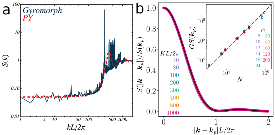
To further investigate the nature of order in gyromorphs, we replot a structure factor in log-log scales in Fig. 2. This panel shows that gyromorphs are not hyperuniform, as the low- limit of saturates at a level similar to that of a Percus-Yevick model for equilibrium hard disk liquids [46]. We further validate this observation by measuring local number fluctuations in real space over windows of increasing size [16, 35] (see Appendix), finding that the long-range density fluctuation scaling of gyromorphs is indistinguishable from that of hard disks. Furthermore, at large , the decay of is also similar to that of a liquid. These results suggest that, with respect to translational order, gyromorphs are more akin to liquids than to quasicrystals.
In Fig. 2, we analyze the peaks. In the main panel, we show the profile of the peak at , normalized by its height, as a function of the distance to the maximum, across system sizes for . As grows, the profile converges to , implying that the linear width of the peaks in -space decays like . The inset shows that, for different values of , the peak heights grow like , indicating that the peaks are extensive for any fixed order symmetry. Altogether, the peaks have extensive height while their area decays like : they approach Dirac deltas as increases, like in quasicrystals, so that gyromorphs display quasi-long-range rotational order (see Appendix).
Coupled Dipoles Method – We now turn our attention to the optical properties of gyromorphs. From an Ewald-sphere construction [47, 48] one expects a ring of many high peaks at radius to generate strong backscattering at [33]. That is why quasicrystals were deemed good candidates for isotropic bandgaps. However, they display increasingly shallow bandgaps as their order of rotational symmetry grows [10], which can be attributed to weakening features in in de Bruijn’s construction [38, 39] as increases. By contrast, gyromorphs are only constrained to display a finite set of high fine peaks, and they may retain a deep isotropic bandgap even at high .

To verify this, we assume that each point in the gyromorph represents a non-magnetic scatterer with a dielectric contrast from the surrounding medium at pulsation , corresponding to a refractive index , and a radius . Limiting our analysis to wave-vectors (with the celerity of waves in the host medium) such that (Rayleigh scattering [42]), we employ a coupled dipoles approximation to describe the scattering of waves by the structure. This standard method [40, 41, 42] turns the problem of solving Maxwell’s equations in the medium (a very strenuous task that involves a full discretization of space as well as very specific choices of boundary conditions [49, 50]) into a linear system, see Appendix. In short, setting only and for the scatterers, we measure transmitted intensities for any choice of monochromatic source field, as well as an integrated local density of optical states (LDOS). Throughout the main text, we present results for vector waves (Transverse Electric, or TE, mode in , as opposed to the scalar-wave Transverse Magnetic, or TM, mode). We report the scalar-wave results in SM [37], as scalar-wave bandgaps are less challenging to obtain in point patterns [10, 17, 23, 15]. All optical properties are computed within the Materials Analysis via Green’s Tensors (MAGreeTe) library, which we make publicly available [51].
Existence of a bandgap – First, in Fig. 3, we focus on a single gyromorph with and to determine whether a bandgap is present. We first trim the system to a circular shape of radius to avoid any anisotropy due to the overall shape of the medium, like in many experimental tests [9, 17, 18]. We then set the radius of scatterers such that the filling fraction equals and the dielectric contrast ( for scatterers in vacuum), a typical value for metal oxides used in experiments [22]. Following Refs. [9, 17, 18, 22], we first perform transmission measurements. We set the source to be a standard Gaussian beam with zero curvature focused at the center of the medium [52, 53, 42]. We solve the coupled dipoles system for regularly spaced orientations of the beam and for several frequencies . Then, following Refs. [52], we measure the transmitted intensity behind the system at a distance from its nearest edge 111The reason for not measuring the transmission in the far field is that the monochromatic Gaussian beam is not in fact a physical laser beam, in the sense that its intensity does not decay according to the Rayleigh-Sommerfeld boundary condition in the far field [42].. For each incoming beam orientation , we define the transmission as the average intensity over 180 angles in on the half-circle with radius , normalized by the value of the incident field at these points in the absence of the medium [37]. The results, shown in Fig. 3 in the plane of incident wave-vectors , display a clear trough of low intensities at , as expected from single-scattering arguments [33, 35]. An intensity map for and is shown in Fig. 3, confirming that the field is strongly backscattered. To confirm that this lower transmission is the sign of a bandgap, we measure the DOS of the system. In Fig. 3, we show , the relative change of DOS compared to vacuum averaged over random points drawn randomly across the material but at least away from scatterers, following Refs. [55, 14]. We show strong mode depletion at . Finally, a map of the local across the system in Fig. 3 shows consistent mode depletion across the bulk. These results are confirmed by standard but costlier finite-difference methods [49] in small systems in SM [37], where we also show similar TM results.

Comparison to other systems – We compare the results of Fig. 3 to classic bandgap candidates, namely - and -fold deterministic quasicrystals obtained by the de Bruijn’s construction [38, 39, 56, 37], a deterministic Vogel spiral [4], and a random SHU structure generated by FReSCo [35] with a degree of stealthiness such that it displays a TM bandgap [17, 18, 29, 14, 15, 21, 37]. Structures are adjusted to contain points and a ring of higher values at the same as the gyromorphs, and we set all parameters to the same values as in Fig. 3. We report transmission plots in the top row of Fig. 4, and DOS in the bottom row. We show that Vogel and SHU systems display much shallower transmission troughs than the gyromorphs, which we attribute to weaker features in , and very little DOS change. Furthermore, we show that quasicrystals may either display rather deep but anisotropic gaps at low symmetries, or isotropic but shallow gaps at high symmetry due to the broadening of their features [10, 37]. In fact, the bandgaps of finite-size gyromorphs are as deep as in low-order quasicrystals but more isotropic than them at comparable . We check [37] that the DOS dip in gyromorphs gets deeper with index contrast and system size (following a power law, like in defective crystals or SHU structures [57, 14, 58]), but does not strongly depend on .

Extension to – We now extend the concept of gyromorphs to structures. We optimize structures to display regularly spaced peaks on a sphere with radius in their structure factor. As there is no standardized way to populate points evenly spaced on a sphere while preserving centrosymmetry, we choose the location of peaks by building upon icosahedral geometry. Starting from an icosahedron of peaks, we subdivide each icosahedral face into multiple triangular faces and project those additional vertices onto the sphere. An example of such a set of peaks is shown in Fig. 5. We show in Fig. 5 cross-sections of the for a gyromorph thus obtained with . Finally, in Fig. 5, we show optical properties measured for this system, namely a transmission plot and the averaged relative change of LDOS for vector waves. We report an isotropic transmission gap, that is correlated to a depletion of DOS, which shows that gyromorphs are promising bandgap formers.

Beyond one ring – Finally, we extend the concept of gyromorphs to disordered systems displaying several rings of peaks. An example system is shown in Fig. 6, where we impose rings of mutually prime (up to parity) rotational orders, at distances with irrational ratios to ensure that the structure is not trivially compatible with a single (quasi)crystal. The resulting structure factor and pair correlation function are shown in Fig. 6 and , respectively. This structure is expected to display consecutive dips in transmission and DOS, which we indeed report in Fig. 6 and . This example highlights that gyromorphs are much more general than “dual quasicrystals” and can be used to obtain arbitrary transmission gaps in an aperiodic medium.
Conclusion – We introduced a novel class of disordered materials, termed gyromorphs, which are translationally disordered but exhibit one (or several) ring of delta peaks, resulting in quasi-long-range discrete rotational order. We showed that gyromorphs with high rotational order exhibit deeper isotropic bandgaps than systems previously considered in the literature, in both 2d and 3d, and that several such features can be imposed at once. This advance is significant both fundamentally and practically. Fundamentally, we conceived and verified the existence of a new class of structures that reconciles seemingly contradictory features and stands apart from all known material types. Practically, our numerical predictions indicate that gyromorphs outperform existing isotropic photonic bandgap materials. Gyromorphs thus show promise for applications such as freeform waveguides [1, 2] and lightweight coatings with strong backscattering, such as highly reflective “white” structures [59, 60].
Acknowledgements.
Acknowledgments – The authors would like to thank Weining Man, Paul Chaikin, Dov Levine, Rémi Carminati, Luís Froufe-Pérez, Frank Scheffold, and Werner Krauth for insightful comments on this work. A.S., M.C., and S.M. acknowledge the Simons Center for Computational Physical Chemistry for financial support. This work was supported in part through the NYU IT High Performance Computing resources, services, and staff expertise. Parts of the results in this work make use of the colormaps in the CMasher package [61]. Correlations are computed using the rusted_core library. The FReSCo, MAGreeTe, and rusted-core libraries are publically available [62, 51, 63].References
- Man et al. [2013a] W. Man, M. Florescu, E. P. Williamson, Y. He, S. R. Hashemizad, B. Y. Leung, D. R. Liner, S. Torquato, P. M. Chaikin, and P. J. Steinhardt, Isotropic band gaps and freeform waveguides observed in hyperuniform disordered photonic solids, Proceedings of the National Academy of Sciences of the United States of America 110, 15886 (2013a).
- Milošević et al. [2019] M. M. Milošević, W. Man, G. Nahal, P. J. Steinhardt, S. Torquato, P. M. Chaikin, T. Amoah, B. Yu, R. A. Mullen, and M. Florescu, Hyperuniform disordered waveguides and devices for near infrared silicon photonics, Scientific Reports 9, 20338 (2019).
- Piechulla et al. [2021] P. M. Piechulla, E. Slivina, D. Bätzner, I. Fernandez-Corbaton, P. Dhawan, R. B. Wehrspohn, A. N. Sprafke, and C. Rockstuhl, Antireflective Huygens’ Metasurface with Correlated Disorder Made from High-Index Disks Implemented into Silicon Heterojunction Solar Cells, ACS Photonics 8, 3476 (2021).
- Vogel [1979] H. Vogel, A Better Way to Construct the Sunflower Head, Mathematical Biosciences 44, 179 (1979).
- Pollard and Parker [2009] M. E. Pollard and G. J. Parker, Low-contrast bandgaps of a planar parabolic spiral lattice, Optics Letters 34, 2805 (2009).
- Liew et al. [2012] S. F. Liew, H. Noh, J. Trevino, L. D. Negro, and H. Cao, Localized photonic band edge modes and orbital angular momenta of light in a golden-angle spiral, Optics InfoBase Conference Papers 19, 23631 (2012).
- Trevino et al. [2012] J. Trevino, S. F. Liew, H. Noh, H. Cao, and L. Dal Negro, Geometrical structure, multifractal spectra and localized optical modes of aperiodic Vogel spirals, Optics Express 20, 3015 (2012).
- Razo-López et al. [2024] L. A. Razo-López, G. J. Aubry, F. A. Pinheiro, and F. Mortessagne, Strong localization of microwaves beyond two dimensions in aperiodic Vogel spirals, Physical Review B 109, 014205 (2024).
- Man et al. [2005] W. Man, M. Megens, P. J. Steinhardt, and P. M. Chaikin, Experimental measurement of the photonic properties of icosahedral quasicrystals, Nature 436, 993 (2005).
- Rechtsman et al. [2008] M. C. Rechtsman, H. C. Jeong, P. M. Chaikin, S. Torquato, and P. J. Steinhardt, Optimized structures for photonic quasicrystals, Physical Review Letters 101, 073902 (2008).
- Vardeny et al. [2013] Z. V. Vardeny, A. Nahata, and A. Agrawal, Optics of photonic quasicrystals, Nature Photonics 7, 177 (2013).
- Yu et al. [2021] S. Yu, C. W. Qiu, Y. Chong, S. Torquato, and N. Park, Engineered disorder in photonics, Nature Reviews Materials 6, 226 (2021).
- Vynck et al. [2023] K. Vynck, R. Pierrat, R. Carminati, L. S. Froufe-Pérez, F. Scheffold, R. Sapienza, S. Vignolini, and J. J. Sáenz, Light in correlated disordered media, Reviews of Modern Physics 95, 045003 (2023).
- Froufe-Pérez et al. [2017] L. S. Froufe-Pérez, M. Engel, J. J. Sáenz, and F. Scheffold, Band gap formation and Anderson localization in disordered photonic materials with structural correlations, Proceedings of the National Academy of Sciences of the United States of America 114, 9570 (2017).
- Monsarrat et al. [2022] R. Monsarrat, R. Pierrat, A. Tourin, and A. Goetschy, Pseudogap and Anderson localization of light in correlated disordered media, Physical Review Research 4, 033246 (2022).
- Torquato [2018] S. Torquato, Hyperuniform states of matter, Physics Reports 745, 1 (2018).
- Florescu et al. [2009a] M. Florescu, S. Torquato, and P. J. Steinhardt, Designer disordered materials with large, complete photonic band gaps, Proceedings of the National Academy of Sciences of the United States of America 106, 20658 (2009a).
- Man et al. [2013b] W. Man, M. Florescu, K. Matsuyama, P. Yadak, G. Nahal, S. Hashemizad, E. Williamson, P. Steinhardt, S. Torquato, and P. Chaikin, Photonic band gap in isotropic hyperuniform disordered solids with low dielectric contrast, Optics Express 21, 19972 (2013b).
- Muller et al. [2014] N. Muller, J. Haberko, C. Marichy, and F. Scheffold, Silicon hyperuniform disordered photonic materials with a pronounced gap in the shortwave infrared, Advanced Optical Materials 2, 115 (2014).
- Tsitrin et al. [2015] S. Tsitrin, E. P. Williamson, T. Amoah, G. Nahal, H. L. Chan, M. Florescu, and W. Man, Unfolding the band structure of non-crystalline photonic band gap materials, Scientific Reports 5, 13301 (2015).
- Klatt et al. [2022] M. A. Klatt, P. J. Steinhardt, and S. Torquato, Wave propagation and band tails of two-dimensional disordered systems in the thermodynamic limit, Proceedings of the National Academy of Sciences of the United States of America 119, e2213633119 (2022).
- Siedentop et al. [2024] L. Siedentop, G. Lui, G. Maret, P. M. Chaikin, P. J. Steinhardt, S. Torquato, P. Keim, and M. Florescu, Stealthy and hyperuniform isotropic photonic bandgap structure in 3D, Arxiv Preprint , 2403.08404 (2024), arXiv:2403.08404 .
- Florescu et al. [2009b] M. Florescu, S. Torquato, and P. J. Steinhardt, Complete band gaps in two-dimensional photonic quasicrystals, Physical Review B - Condensed Matter and Materials Physics 80, 155112 (2009b).
- Zheng et al. [2020] Y. Zheng, L. Liu, H. Nan, Z. X. Shen, G. Zhang, D. Chen, L. He, W. Xu, M. Chen, Y. Jiao, and H. Zhuang, Disordered hyperuniformity in two-dimensional amorphous silica, Science Advances 6, eaba0826 (2020).
- Froufe-Pérez et al. [2023] L. S. Froufe-Pérez, G. J. Aubry, F. Scheffold, and S. Magkiriadou, Bandgap fluctuations and robustness in two-dimensional hyperuniform dielectric materials, Optics Express 31, 18509 (2023).
- Yang et al. [2010] J. K. Yang, C. Schreck, H. Noh, S. F. Liew, M. I. Guy, C. S. O’Hern, and H. Cao, Photonic-band-gap effects in two-dimensional polycrystalline and amorphous structures, Physical Review A - Atomic, Molecular, and Optical Physics 82, 053838 (2010).
- Liew et al. [2011] S. F. Liew, J. K. Yang, H. Noh, C. F. Schreck, E. R. Dufresne, C. S. O’Hern, and H. Cao, Photonic band gaps in three-dimensional network structures with short-range order, Physical Review A - Atomic, Molecular, and Optical Physics 84, 063818 (2011).
- Djeghdi et al. [2022] K. Djeghdi, U. Steiner, and B. D. Wilts, 3D Tomographic Analysis of the Order-Disorder Interplay in the Pachyrhynchus congestus mirabilis Weevil, Advanced Science 9, 2202145 (2022).
- Froufe-Pérez et al. [2016] L. S. Froufe-Pérez, M. Engel, P. F. Damasceno, N. Muller, J. Haberko, S. C. Glotzer, and F. Scheffold, Role of Short-Range Order and Hyperuniformity in the Formation of Band Gaps in Disordered Photonic Materials, Physical Review Letters 117, 1 (2016).
- Sellers et al. [2017] S. R. Sellers, W. Man, S. Sahba, and M. Florescu, Local self-uniformity in photonic networks, Nature Communications 8, 14439 (2017).
- Klatt et al. [2019] M. A. Klatt, P. J. Steinhardt, and S. Torquato, Phoamtonic designs yield sizeable 3D photonic band gaps, Proceedings of the National Academy of Sciences of the United States of America 116, 23480 (2019).
- Chan et al. [1998] Y. S. Chan, C. T. Chan, and Z. Y. Liu, Photonic band gaps in two dimensional photonic quasicrystals, Physical Review Letters 80, 956 (1998).
- Hagelstein and Denison [1999] P. L. Hagelstein and D. R. Denison, Nearly isotropic photonic bandgap structures in two dimensions, Optics Letters 24, 708 (1999).
- Della Villa et al. [2005] A. Della Villa, S. Enoch, G. Tayeb, V. Pierro, V. Galdi, and F. Capolino, Band gap formation and multiple scattering in photonic quasicrystals with a penrose-type lattice, Physical Review Letters 94, 183903 (2005).
- Shih et al. [2024] A. Shih, M. Casiulis, and S. Martiniani, Fast Generation of Spectrally-Shaped Disorder, Physical Review E 110, 034122 (2024).
- Levine and Steinhardt [1984] D. Levine and P. J. Steinhardt, Quasicrystals: A new class of ordered structures, Physical Review Letters 53, 2477 (1984).
- [37] URL_will_be_inserted_by_publisher.
- De Bruijn [1981] N. De Bruijn, Algebraic theory of Penrose’s non-periodic tilings of the plane . I , II : dedicated to G. Pólya, Indagationes Mathematicae 43, 39 (1981).
- de Bruijn [1986] N. de Bruijn, Quasicrystals and their Fourier transform, Indagationes Mathematicae (Proceedings) 89, 123 (1986).
- Lax [1951] M. Lax, Multiple Scattering of Waves, Reviews of Modern Physics 23, 287 (1951).
- Lax [1952] M. Lax, Multiple scattering of waves. II. the effective field in dense systems, Physical Review 85, 621 (1952).
- Carminati and Schotland [2021] R. Carminati and J. C. Schotland, Principles of Scattering and Transport of Light (Cambridge University Press, 2021).
- Steinhardt et al. [1983] P. J. Steinhardt, D. R. Nelson, and M. Ronchetti, Bond-orientational order in liquids and glasses, Physical Review B 28, 784 (1983).
- Chen et al. [2011] Y. F. Chen, H. C. Liang, Y. C. Lin, Y. S. Tzeng, K. W. Su, and K. F. Huang, Generation of optical crystals and quasicrystal beams : Kaleidoscopic patterns and phase singularity, Physical Review A 83, 053813 (2011).
- Tuan and Huang [2023] P.-H. Tuan and L.-Q. Huang, Optical vector fields with kaleidoscopic quasicrystal structures by multiple beam interference, Optics Express 31, 33077 (2023).
- Rosenfeld [1990] Y. Rosenfeld, Free-energy model for the inhomogeneous hard-sphere fluid in D dimensions: Structure factors for the hard-disk (D=2) mixtures in simple explicit form, Physical Review A 42, 5978 (1990).
- Ewald [1921] P. P. Ewald, Die Berechnung optischer und elektrostatischer Gitterpotentiale, Annalen der Physik 369, 253 (1921).
- Kittel [1953] C. Kittel, Introduction to Solid-state Physics (John Wiley & Sons, New York, 1953).
- Oskooi et al. [2010] A. F. Oskooi, D. Roundy, M. Ibanescu, P. Bermel, J. D. Joannopoulos, and S. G. Johnson, Meep: A flexible free-software package for electromagnetic simulations by the FDTD method, Computer Physics Communications 181, 687 (2010).
- Yamilov et al. [2023] A. Yamilov, S. E. Skipetrov, T. W. Hughes, M. Minkov, Z. Yu, and H. Cao, Anderson localization of electromagnetic waves in three dimensions, Nature Physics 19, 1308 (2023).
- Casiulis et al. [2024] M. Casiulis, A. Shih, and S. Martiniani, Materials Analysis via Greene Tensors (MAGreeTe) (2024).
- Leseur et al. [2014] O. Leseur, R. Pierrat, J. J. Sáenz, and R. Carminati, Probing two-dimensional Anderson localization without statistics, Physical Review A - Atomic, Molecular, and Optical Physics 90, 053827 (2014).
- Leseur et al. [2016] O. Leseur, R. Pierrat, and R. Carminati, High-density hyperuniform materials can be transparent, Optica 3, 763 (2016).
- Note [1] The reason for not measuring the transmission in the far field is that the monochromatic Gaussian beam is not in fact a physical laser beam, in the sense that its intensity does not decay according to the Rayleigh-Sommerfeld boundary condition in the far field [42].
- Pierrat and Carminati [2010] R. Pierrat and R. Carminati, Spontaneous decay rate of a dipole emitter in a strongly scattering disordered environment, Physical Review A - Atomic, Molecular, and Optical Physics 81, 063802 (2010).
- Lutfalla [2021] V. H. Lutfalla, An effective construction for cut-and-project rhombus tilings with global n-fold rotational symmetry, in 27th IFIP WG 1.5 International Workshop on Cellular Automata and Discrete Complex Systems (AUTOMATA 2021), 9, edited by A. Castillo-Ramirez, P. Guillon, and K. Perrot (Schloss Dagstuhl – Leibniz-Zentrum für Informatik, Dagstuhl Publishing, Germany, 2021) pp. 9:1–9:12.
- Skipetrov [2016] S. E. Skipetrov, Finite-size scaling analysis of localization transition for scalar waves in a three-dimensional ensemble of resonant point scatterers, Physical Review B 94, 064202 (2016).
- Skipetrov [2020] S. E. Skipetrov, Finite-size scaling of the density of states inside band gaps of ideal and disordered photonic crystals, European Physical Journal B 93, 70 (2020).
- Burresi et al. [2014] M. Burresi, L. Cortese, L. Pattelli, M. Kolle, P. Vukusic, D. S. Wiersma, U. Steiner, and S. Vignolini, Bright-white beetle scales optimise multiple scattering of light, Scientific Reports 4, 1 (2014).
- Wilts et al. [2018] B. D. Wilts, X. Sheng, M. Holler, A. Diaz, M. Guizar-Sicairos, J. Raabe, R. Hoppe, S. H. Liu, R. Langford, O. D. Onelli, D. Chen, S. Torquato, U. Steiner, C. G. Schroer, S. Vignolini, and A. Sepe, Evolutionary-Optimized Photonic Network Structure in White Beetle Wing Scales, Advanced Materials 30, 201702057 (2018).
- van der Velden [2020] E. van der Velden, CMasher: Scientific colormaps for making accessible, informative and ’cmashing’ plots, Journal of Open Source Software 5, 2004 (2020).
- Shih et al. [2023] A. Shih, M. Casiulis, and S. Martiniani, Fast Reciprocal-Space Correlator (FReSCo) (2023).
- Casiulis [2023] M. Casiulis, rusted_core (2023).
- Pilleboue et al. [2015] A. Pilleboue, G. Singh, D. Coeurjolly, M. Kazhdan, and V. Ostromoukhov, Variance analysis for Monte Carlo integration, ACM Transactions on Graphics 34, 124 (2015).
- Bernard et al. [2009] E. P. Bernard, W. Krauth, and D. B. Wilson, Event-chain Monte Carlo algorithms for hard-sphere systems, Physical Review E - Statistical, Nonlinear, and Soft Matter Physics 80, 5 (2009).
- Cazé et al. [2013] A. Cazé, R. Pierrat, and R. Carminati, Strong coupling to two-dimensional Anderson localized modes, Physical Review Letters 111, 053901 (2013).

Gyromorphs are not hyperuniform– In the main text, we claim that gyromorphs are not hyperuniform based on results presented in Figs. 1 and 2. We present further evidence of this in Fig. 7, where we perform discrepancy measurements for disks [64, 16, 35]. To do so, we draw random disks with radius at uniform positions within -fold gyromorphs and count the number of points that each disk contains. We then measure the mean number and the variance of this number using disks, and compute the reduced variance for each . The output is shown when varying for in Fig. 7, where is plotted against in logarithmic scales. We show that gyromorphs display number fluctuations close to Poissonian () at small length scales, then feature sub-Poissonian fluctuations at ranges larger than . While the behaviour is non-Poissonian, the slope is much weaker than that of stealthy hyperuniform systems (). In fact, we show that gyromorphs are near-indistinguishable from equilibrium hard disk liquids, using data from an equilibrium configuration obtained by Event-Chain Monte Carlo [65]. This conclusively shows that gyromorphs are not hyperuniform, even in the largest systems we test, . We show in Fig. 7 that this result holds when scanning values of at a fixed , even at rotational symmetries of order as low as -fold, where gyromorphs may more easily be confused [35] with quasicrystals (which follow the stealthy scaling [16]).

Gyromorphs and Quasicrystals – We here further discuss the differences and commonalities between gyromorphs and quasicrystals. First, we produce a -fold quasicrystal by de Bruijn’s method [38, 39], and report its in Fig. 8, respectively as an intensity map in -space and as a radially-averaged function of . The structure factor is patterned up to very large , resulting in peaks with near-constant (but slowly decaying) intensity in the radial plot. We use this structure as an initial condition for our algorithm, aiming to enhance the height of the existing first ring of high quasicrystalline peaks (indicated by the arrow in Fig. 8). The result, whose is shown in Fig. 8 is indistinguishable from what we obtain from random initial conditions. In particular, note that the large- structure in is completely destroyed: the far-away pattern has been “pumped” into the peaks to make them (about 3 times) higher, as highlighted by a red dashed line. This experiment shows that gyromorphs, the minima of our loss function, are not simply noisy quasicrystals but do in fact display stronger peaks even at small . Furthermore, gyromorphs are not simply entropically more favorable than quasicrystals, they actually better minimize our loss function.

This difference becomes starker at larger orders of rotational symmetry, as the height of the peaks of de Bruijn quasicrystals decays fast with [10]. However, we highlight an interesting link between gyromorphs and quasicrystals in Fig. 9, where we show side-by-side comparisons of these two quantities for in panels Fig. 9,, and in panels Fig. 9,. All systems were made using points. The quasicrystals are constructed using de Bruijn’s multigrid and dual method [38, 39, 56]. The panels show near-perfect agreement between the real (resp. reciprocal) features of gyromorphs and the reciprocal (resp. real) features of quasicrystals. In other words, gyromorphs look like duals of quasicrystals. This is because the of gyromorphs (resp. the of quasicrystals) is dominated by one ring of high peaks, so that its Fourier transform is well approximated by a sum of cosines.
To highlight that gyromorphs display quasi-long-range rotational order, in Fig. 10, we plot a gyromorphic correlation function, , defined as
| (1) |
where the sum runs over all pairs of particles, that are separated by a distance vector with polar components . That is essentially the value of the modulus of the -th Fourier mode of a shell of at distance . When suitably rescaled by , this function collapses across values of , and displays a power-law decay with an exponent close to . We show in Fig. 10 a comparison of that function between a gyromorph and the corresponding quasicrystal, with taken as the location of the strongest peak. The difference is mainly that quasicrystals display strong rotational order with nearest neighbors, as they lie on a discrete set of orientations along a rhombic tiling, while gyromorphs are isotropic at short range. The long-range behavior, however, is nearly the same. Thus, gyromorphs display quasi-long-range rotational order, that extends throughout the system [35, 37].


Coupled dipoles in a nutshell – If represents the position of scatterer , is the -component of the Fourier representation of an arbitrary incident field at and is the total exciting field at scatterer , this system can be written as
| (2) |
where we introduced rank- tensor notations for the values of both kinds of fields so that for instance with , and is rank- with elements
| (3) |
In this last expression, is the polarizability of a scatterer with volume , is a self-interaction term that ensures energy conservation and is the Green tensor of free propagation with the desired boundary conditions (here, Rayleigh-Sommerfeld ones [42]). Solving Eq. 2 for vector waves with components reduces to a linear solve yielding where . From that solution, the full electromagnetic field at any position outside of scatterers can be reconstructed as
| (4) |
where is a rank- tensor with elements . In practice, we use
| (5) |
with the components of parallel and perpendicular to a beam with width , respectively. Finally, to assert the presence of bandgaps, we compute the local density of optical states (LDOS)
| (6) |
The coupled dipoles method lets us compute the relative change of LDOS compared to the vacuum value, , as the trace of a tensor product.
| (7) |
where we dropped the dependence from the tensor notations for compactness and . Following past works [55, 66, 14], we estimate the DOS of the medium at points at least away from scatterer centers, and average the result over random points in the medium. We remind the standard [42] derivation of these equations and the precise definitions of every term in and in SM [37].