Demonstrating real-time and low-latency quantum error correction with superconducting qubits
Abstract
Quantum error correction (QEC) will be essential to achieve the accuracy needed for quantum computers to realise their full potential. The field has seen promising progress with demonstrations of early QEC and real-time decoded experiments. As quantum computers advance towards demonstrating a universal fault-tolerant logical gate set, implementing scalable and low-latency real-time decoding will be crucial to prevent the backlog problem, avoiding an exponential slowdown and maintaining a fast logical clock rate. Here, we demonstrate low-latency feedback with a scalable FPGA decoder integrated into the control system of a superconducting quantum processor. We perform an 8-qubit stability experiment with up to decoding rounds and a mean decoding time per round below \unit\micro, showing that we avoid the backlog problem even on superconducting hardware with the strictest speed requirements. We observe logical error suppression as the number of decoding rounds is increased. We also implement and time a fast-feedback experiment demonstrating a decoding response time of \unit\micro for a total of measurement rounds. The decoder throughput and latency developed in this work, combined with continued device improvements, unlock the next generation of experiments that go beyond purely keeping logical qubits alive and into demonstrating building blocks of fault-tolerant computation, such as lattice surgery and magic state teleportation.
I Introduction

Quantum computers have the potential to perform computations that are beyond the capabilities of classical computers [1, 2]. However, various quantum algorithms that offer an advantage over classical algorithms will require hundreds of qubits and over a billion operations [3, 4, 5, 6], which are prone to errors. To combat the noise and unlock the potential of such algorithms, quantum error correction (QEC) will be necessary. QEC encodes the information we want to protect by distributing it across multiple qubits and repeatedly generating data characterising quantum errors [7, 8, 9]. Classical algorithms, known as decoders, use this data to identify errors that occurred during quantum computation. At low enough physical error rates, QEC suppresses errors when executing quantum algorithms, offering a path towards practical quantum computation. However, QEC codes alone cannot implement a universal and transversal gate set [10]. Leading proposals for implementing non-Clifford gates require logical branching – a logical operation conditional on a corrected observable, which is computed by combining the measured value of the observable and the logical correction returned by the decoder. For example, on the surface code [11, 12, 13], a logical gate can be implemented via teleportation and magic state injection [14, 15, 16], which requires a conditional logical gate. Since logical branching happens during circuit execution and depends on the decoding result, this places throughput and latency requirements on the decoding process.
The rate at which the decoder processes data (the throughput) needs to be greater than the rate at which data is generated, which on superconducting devices can be as fast as one data extraction round per \unit\micro [17, 18, 19, 20]. This is necessary to avoid the backlog problem [7], i.e., an exponential slowdown of the quantum computation due to a growing backlog of data at each decoding iteration. High throughput can be achieved both with fast decoders and by parallelizing the decoding workload over many decoder threads [21, 22, 23, 24, 25]. However, parallelization strategies will be limited by [21] a second key parameter: the full decoding response time, which is the time between the final data extraction round and the application of a logical conditional gate. This response time includes the decoding time as well as the communication and control latency times to send the data to and from the decoder. This parameter can be a significant speed bottleneck for operations involving logical branching such as logical non-Clifford gates on surface codes [14, 15, 16]. As a result, it directly affects the logical clock rate (i.e., the inverse of the time required to perform a single logical non-Clifford gate), another QEC metric that determines the execution speed of fault-tolerant algorithms. Reducing both the decoding time and the communication and control latency to minimize the full decoding response time is key to ensure that complex quantum algorithms are executed within reasonable times. For example, when estimating that -bit RSA integers can be factored in 8 hours using 20 million noisy superconducting qubits, the authors assume a full decoding response time within \unit\micro [3]. To ensure fast decoding response time it is important to decode in real time, meaning that data is passed to the decoder and processed as soon as it becomes available. This contrasts with offline decoding, where the decoding can be performed at any time after the data has been collected. Real-time decoding has been experimentally demonstrated but with decoding response times far exceeding the \unit\micro goal [26, 25] or using an unscalable lookup table approach [26, 27, 28, 29].
In this work, we present a real-time decoded QEC experiment on qubits with logical branching that measures the full decoding response time to be \unit\micro, including \unit\micro decoding time and \unit\micro communication and control latency times, per measurement rounds. We achieve this by decoding with a scalable FPGA implementation of a Collision Clustering decoder [30], integrated into Rigetti’s Ankaa™-2 superconducting device’s control system (Fig.˜1). We demonstrate decoding times per QEC cycle faster than the \unit\micro threshold for generating measurement data on a superconducting qubit device, ensuring the backlog problem is avoided, and show logical error suppression for a so-called stability experiment [31] with up to decoding rounds. The ability of our decoding system to avoid the backlog problem and maintain low-latency feedback opens the door for experiments involving logical branching, which will be vital for implementing a fault-tolerant universal gate set.
II Stability experiment on a surface code
In this study, we focus on the stability experiment [31] implemented with the rotated planar surface code, which is one of the most promising QEC codes due to its high threshold and nearest-neighbour hardware-connectivity requirements [11, 12, 13]. The practical implementation of fault-tolerant gates on the surface code has also been extensively studied and developed [32, 16, 33, 34, 35]. To realize a QEC protocol, Pauli operators called stabilizers are repeatedly measured to detect physical errors. For the rotated surface code, the stabilizer set consists of weight or tensor products of or operators arranged on a 2D square lattice of qubits. A detector is a product of stabilizer measurements, whose value is deterministic in the case of no errors [36]. For example, we typically assign a detector to the product of consecutive measurements of the same stabilizer. A detector whose value has been flipped from the one expected in the case of no errors is referred to as a defect. Therefore, defects signal the presence of errors. The defect rate is the probability of observing a defect. A syndrome is the set of values of detectors observed during an experiment.
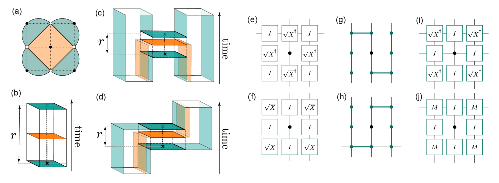
A stability experiment [31] tests the capability of a quantum processing unit (QPU) to preserve an observable in space by correctly measuring products of stabilizers (Fig.˜2(a,b)). Surface code operations such as lattice surgery [32, 37] (Fig.˜2(c)), logical qubit patch movement [16] (Fig.˜2(d)) or the logical Hadamard gate [38, 39] all involve measuring products of stabilizers. In these examples, incorrectly measuring the stabilizer product can introduce a logical error. For instance, in lattice surgery, this stabilizer product determines the logical branching decisions when performing non-Clifford gates, with a logical error meaning the wrong branch is followed. The stability experiment [31] verifies the ability to protect against these logical errors and in this work acts as a smaller-scale simulation of logical branching experiments. Such an experiment on a surface code-like patch is performed with an over-complete set of stabilizers whose product is equal to the identity, yet not assigned as a detector. We will refer to this product of stabilizers as a logical observable [36]. In the absence of errors, the logical observable is necessarily measured as . This means that we can verify the ability of a QEC scheme to correctly deduce whether the logical observable has been flipped. For a stability experiment at low enough physical error rates, the logical error probability is suppressed as the number of decoding rounds is increased.
In this work, we focus on real-time decoding of a stability experiment only measuring an overcomplete set of 4 stabilizers of form, and omitting the single stabilizer that plays no role in decoding. This omission simplifies the syndrome extraction circuit and leads to improved logical error rates. We refer to this experiment as the stability- experiment. Fig.˜2(e) shows the data qubit preparation at the start of the experiment. To obtain a single round of syndrome data, we use the syndrome extraction circuit shown in Fig.˜2(f–j), where steps (f–i) map the product of stabilizers to the ancilla qubits, which are then measured in step (j). The measurement outcomes are aggregated to pre-defined detector outcomes, which are inputs to the decoder.
III Integrating an FPGA decoder in the Ankaa-2 control system
We decode with an FPGA decoder integrated into the Ankaa-2 control system (more details on the integration work are given in Methods). Ankaa-2 is a superconducting transmon qubit device, with qubits arranged on a square lattice, and two-qubit gates implemented via tunable couplers [40, 41, 42] (see Methods for details on the Ankaa-2 device). The decoder we use is an FPGA implementation of a Collision Clustering decoder [30], which achieves the same logical fidelities as the Union Find algorithm [43]. Modifications were made to the FPGA decoder of Ref. [30] to allow for decoding the stability experiment and syndrome extraction circuits without mid-circuit reset operations [44, 45, 46]. The FPGA decoder is optimised for speed and scalability to larger systems. The decoder executes at MHz frequency on one of the sequencers responsible for gate pulses on the Ankaa-2 control system (see Methods for more details). It has also been verified for operating at MHz frequency, allowing room for further speed improvements compared to those demonstrated here.
The communication between the FPGA decoder and the rest of the control system is performed via custom assembly language-level instructions. We built a prototype compiler that receives a pyQuil [47] program and adds the necessary instructions to perform real-time decoding and store the results (see Supplementary Information, Section D for more details). Our compiler can also merge two pyQuil programs into a logical branching experiment, where the second program is executed conditionally based on a real-time decoded measurement outcome obtained during the first program.
The stabilizer measurement outcomes are automatically passed to the decoder during circuit execution. Once the decoder receives the allocated number of measurements, the measurements are converted to a syndrome and decoding is performed. The decoded result, along with data storing the decoder speed and status, is written to allocated registers. In a logical branching experiment, the FPGA decoder’s result is communicated in real time to gate sequencers which then, conditionally on the received result, execute the second program.
IV Logical error probability suppression
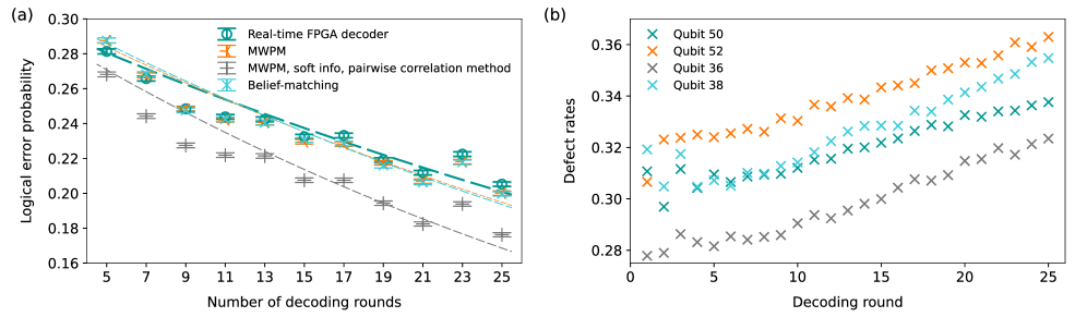
We perform stability-8 experiments on the Ankaa-2 device for varying numbers of QEC rounds, corresponding to to decoding rounds, and decode in real time. We repeat each experiment times to obtain the probability of a logical error persisting at the end of the QEC routine. In Fig.˜3(a), we show that on Ankaa-2 using real-time FPGA decoding the physical error rates are low enough to demonstrate logical error probability suppression with an increasing number of decoding rounds, which is the signature of a successful stability experiment. The logical error probabilities decrease from at decoding rounds to at decoding rounds. We also decode offline with minimum-weight perfect matching (MWPM) [48] and belief-matching [49] decoders (see Methods for more details) and show in Fig.˜3(a) that when using hard measurement data (i.e., the readout signal classified as “0” or “1”), the real-time FPGA decoder results are comparable to these decoders. We also explore decoding with MWPM decoder using soft measurement information (i.e., the in-phase and quadrature components of the raw readout signal) [50] and a decoding graph constructed with the pairwise correlation method [51, 52, 53, 45, 50] (see Supplementary Information, Section C). This decoder achieves the lowest logical error probability, , as using soft information and pairwise correlation methods gives the decoder more detailed information, resulting in higher accuracy decoding. In the future, we expect FPGA decoders to be adaptable so that soft information with the pairwise correlation method could also be used with FPGA decoding.
We observe fluctuations in the logical error probability estimates with varying numbers of decoding rounds, relative to the expected decay; this is likely due to fluctuations in device performance over time which have been previously shown to occur in superconducting circuit devices, such as fluctuations in the coherence times due to two-level systems (TLSs) [54, 55]. Fig.˜3(b) shows a slight increase in defect rates as further measurement rounds are performed, most likely due to a combination of leakage and heating effects. We believe the limitations on the logical error probability reported here to be largely due to the mid-circuit readout fidelity of the ancilla qubits and the fidelity of the gates that were available on the device; the Ankaa-2 processor design was not optimised for these operations in particular. For a more detailed discussion of the device design and relevant error channels, see Methods and Supplementary Information, Section A.
V Decoding throughput
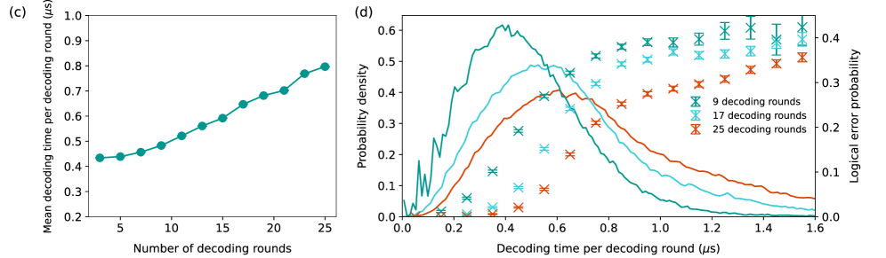
It is necessary to ensure the decoder has a high enough throughput to avoid the backlog problem [7, 21], which arises when data is generated at a faster rate than it can be decoded. If this is not the case, then, because each conditional operation needs to wait for the ever-growing backlog of data to be decoded before it can be applied, each subsequent conditional operation will be exponentially slower, eventually halting the computation. On the Ankaa-2 device, a single round of syndrome extraction takes approximately \unit\micro (see Fig.˜2(f–j)). Other superconducting devices have demonstrated a single round of syndrome extraction of approximately \unit\micro [17, 18, 19, 20]. Fig.˜3(c) shows that our mean decoding time per round ranges from \unit\micro when decoding rounds to \unit\micro when decoding rounds. These values remain below the \unit\micro threshold for data generation on a superconducting qubit device, providing strong evidence that the backlog problem will be avoided when operated as a streaming decoder [21, 23, 22]. The increase in decoding time per round with more decoding rounds is due to the higher noise in later rounds, leading to increased defect rates in deeper circuits (Fig.˜3(b)). As the device improves and the heating and leakage effects are reduced, we expect the mean decoding time per round to grow more slowly as the number of decoding rounds increases. Simulations of the FPGA decoder speed show that the decoding times increase superlinearly with number of decoding rounds, but it is known the scaling can be improved with further optimizations [30]. In the future, we also expect the FPGA decoder to be parallelised, further reducing decoding times.
In Fig.˜3(d), we examine the distribution of the decoding times per round (solid lines) and group experiment repetitions in ns bins, based on their decoding time per round, and plot these against the average logical error probability of the experiments in the bins (crosses). We observe that most of our decoding times are well below \unit\micro per decoding round. Such experiments correspond to a high-likelihood of correctly decoding the syndrome. A small proportion of experiment repetitions exceed the \unit\micro threshold, most likely due to a higher number of defects affecting those experimental runs, which slows down the completion of the decoding. The data represented by crosses indicate that such experiments are associated with worse logical error probabilities.
For practical fault-tolerant computation, we will need lower physical error rates to achieve much lower logical error rates. Lower physical error will lead to lower defect rates and therefore significantly reduce the decoding times. There is also room to more than double the speed of decoding reported in this work, since the FPGA decoder has been verified to be able to operate at MHz, instead of the MHz frequency used in these experiments.
VI Control and communication latencies
We now focus on the full decoding response time, to quantify the contributions of the communication and control latency in our system. We design an experiment that serves as a stepping stone to logical conditional gates. We perform a circuit that conditionally applies a physical gate based on the outcome of decoding the stability- experiment (see Fig.˜4(a)). After the QEC experiment completes and the decoder has received the allocated number of measurement outcomes of the stability circuit, we start the real-time FPGA decoder and wait for the result. When the result is received, we conditionally apply an gate on the qubit controlled by the gate sequencer on the same FPGA as the decoder. The qubit is read out after a fixed delay, set longer than the worst recorded decoding time (approx. for an experiment).
We measure the full decoding response time as a function of the number of QEC rounds (see Fig.˜4(b)). Firstly, we record the FPGA clock cycles on the control system sequencer and the cycles on the decoder accelerator. We note that while the majority of the full decoding response time can be attributed to the decoding time for a larger number of rounds, there is a significant additional latency incurred by the control system delays. In particular, \unit\micro is the time for the final readout results to reach the decoder, with the remaining - \unit\micro ( FPGA clock cycles) consisting of additional control system logic: collecting the measurements into packets to be sent to the decoder, sending them via the WISHBONE bus (see Section˜VIII.2), receiving results and performing the conditional logic (see Supplementary Information, Section D). Furthermore, since the error bars for the timing of the decoder and full control system logic closely match in size, we conclude that the decoding time accounts for the majority of the variance in the full decoding response time.
To check that there are no additional unaccounted delays, we also measure the full decoding response time by using the qubit T1 time as a clock. The measurement distribution after the fixed delay (see Fig.˜4(a)) conditional on the final QEC round readout is a function of the full decoding response time, measurement fidelities, and the qubit’s T1 time (see Supplementary Information, Section E for the detailed derivation). Thus, by collecting the relevant reference data immediately prior to running the feedback experiment, we can estimate the delay experienced by the qubit (see Fig.˜4(b)) which takes into account any delays that might not be measured by the control system clock. With this, we confirm that there are no additional significant delays as the estimated full decoding response time closely matches the one measured by the control system clock.
For a -decoding-round experiment, we find the full decoding response time to be \unit\micro, including \unit\micro decoding time and \unit\micro communication and control latencies. Thanks to the FPGA implementation of our fast decoder and its integration into the Ankaa-2 system, in the small-distance studies reported in this work we keep the full decoding response time within the order of \unit\micro, where is the number of decoding rounds. Maintaining this condition will be crucial when scaling up , as it will ensure that this response time will not be a critical limiting factor for the logical clock speed when implementing non-Clifford operations [21, 23].

VII Discussion
Real-time decoding had been previously demonstrated using lookup table decoders on trapped-ion quantum computers [26, 27], superconducting qubits [28] and a neutral atom device [29]. The memory requirements for lookup table decoders scale exponentially with the number of qubits in the code, meaning that this approach is not feasible for practical fault tolerance, which will require larger codes [16, 4, 5, 6]. The Collision Clustering decoder implementation has been designed to be memory-efficient, with simulations demonstrating that even for distance- memory experiments, the decoder uses less than KB of memory [30].
Recently, the team at Google demonstrated real-time decoding for the distance- memory experiment [25], utilising qubits. In their experiment, the measurement data is sent via Ethernet cable from their control system to a software decoder. They demonstrate high throughput, avoiding the backlog problem, by parallelizing decoding [21, 23, 22]. The reported decoding response time includes an average of \unit\micro to process the final QEC cycle block. They require an additional \unit\micro communication latency to input data to the decoder, and further additional contributions that are not reported including feedback communication latency. Overall, these numbers are significantly slower than our full decoding response time of \unit\micro for a decoding rounds experiment. However, we caution against a direct comparison given the significantly different experimental conditions in which our team’s and Google’s experiments were conducted. Our experiment utilises fewer qubits, while operating at a higher noise regime. These conditions have opposite effects on the decoding time, as the decoding time decreases with smaller code sizes but increases with higher noise in the device. The performance of our FPGA decoder has been extrapolated via simulations to show that, at a noise just below threshold for memory experiments (), the FPGA decoder will be able to maintain a decoding time below \unit\micro per round for memory experiments with distances up to [30]. This, combined with the significant reduction of control and communication latencies achieved by integrating the decoder in the QPU’s control system, suggests that our full decoding response time will remain sufficiently fast to demonstrate larger-scale QEC experiments [3]. We also suggest several strategies for further reducing latency times as the code size is increased. Firstly, readout propagation can be reduced by having a more direct line of communication between readout sequencers and the decoding stack through a standardized interface. Secondly, reordering and packing classified measurements before sending them to the decoder can take up to ns at rounds. In the future, we foresee that such commonly used functionality will have to be offloaded to custom hardware logic attached to the decoder. With these, we do not expect the control system latencies to be a major contributor to the full decoding response time.
VIII Conclusion
The experimental results presented demonstrate an implementation of a decoding protocol that enables next generation QEC experiments requiring logical branching. We report mean decoding times per round under the \unit\micro threshold, avoiding the backlog problem. The fast-feedback experiment shows that integrating an FPGA decoder into the Ankaa-2 control system ensures a low-latency full decoding response time of \unit\micro with a total of decoding rounds for an -qubit experiment.
We show that the logical error probabilities are suppressed in a stability-8 experiment as the number of decoding rounds increases. However, practical fault tolerance will require lower error rates than those reported here. Fine-tuning the readout pulses to be faster and higher fidelity will be essential to achieving this. While resets are not available it will also be beneficial to tune the readout pulses to better preserve the classified state of the qubits. Using resets should improve the results [44] (see exploration of this in Supplementary Information, Section F). Another primary focus should be to increase the ratio of qubit coherence to two-qubit gate duration, along with reducing leakage and other coherent errors.
In the future, fault-tolerant quantum algorithms that have the potential to outperform classical algorithms will require codes utilizing a large number of operations [3, 4, 16, 5, 6]. To support this, the FPGA decoder should be updated to be a streaming decoder [21, 23, 22]. To improve the accuracy of decoding results, we expect future FPGA implementations to enable updates to the decoding graph in real time, allowing for soft-information, leakage-aware decoding [56] or correlated decoding [57]. Combining such advances to decoding and improvements to the device with the methods developed in this work will pave the way for logical operations such as magic state teleportation, enabling fault-tolerant quantum algorithms.
Acknowledgements.
We thank Steve Brierley, Nicolas Didier, Rossy Nguyen, Matthew Reagor, David Rivas, Jake Taylor, Alice Voaden, and Catriona Wright for their support and championing of this project. We thank Maria Maragkou and Luigi Martiradonna for feedback on the manuscript. We thank David Byfield and Mark Turner for advice on implementation and use of analysis tools.Author contributions
L.C., L.S., N.S.B. and A.D.H. led the direction of the project with E.T.C. providing guidance and advice. L.C., L.S., N.S.B. and A.R. implemented the software infrastructure to set up experiments and compile programs for real-time decoding and implemented analysis tools. L.C., L.S., N.S.B. and A.R. ran the experiments and analysed the results. J.A.V and A.D.P. fine-tuned and analysed Ankaa-2 performance and ran experiments. E.T.C., O.C., G.P.G., H.K., E.M., N.I.G. assisted with the theoretical aspects and aided in interpreting the results of the stability experiment. K.J., K.M.B., T.B., O.B., C.T., L.S. contributed to the technical implementation of the FPGA decoder. J.Mc. and G.J. integrated the FPGA decoder into the Ankaa-2 control system. S.P. provided guidance during technical pathfinding. K.S. and M.B. authored novel translation stack features, enabling low-level hardware control through Rigetti’s production stack. A.V.G. implemented resets. J.Ma. implemented soft information decoding. L.C., L.S., N.S.B. and E.T.C. drafted the manuscript and designed the figures with contributions to Methods from J.Mc., J.A.V., A.D.P., A.D.H. and to Supplementary Information from J.A.V., A.D.P., J.Ma., A.R. and A.V.G. Comments and edits were incorporated from all authors. All authors read and approved the final manuscript.
Competing interests
The authors declare no competing interests.
Additional information
Correspondence and requests for materials should be addressed to L.C., L.S. and N.S.B.
References
- Shor [1994] P. Shor, in Proceedings 35th Annual Symposium on Foundations of Computer Science (1994) pp. 124–134.
- Grover [1996] L. K. Grover, in Proceedings of the twenty-eighth annual ACM symposium on Theory of Computing, STOC ’96 (Association for Computing Machinery, New York, NY, USA, 1996) pp. 212–219.
- [3] C. Gidney and M. Ekerå, How to factor 2048 bit RSA integers in 8 hours using 20 million noisy qubits, publisher: Verein zur Förderung des Open Access Publizierens in den Quantenwissenschaften.
- Reiher et al. [2017] M. Reiher, N. Wiebe, K. M. Svore, D. Wecker, and M. Troyer, Proceedings of the National Academy of Sciences 114, 7555 (2017), publisher: Proceedings of the National Academy of Sciences.
- Blunt et al. [2022] N. S. Blunt, J. Camps, O. Crawford, R. Izsák, S. Leontica, A. Mirani, A. E. Moylett, S. A. Scivier, C. Sünderhauf, P. Schopf, J. M. Taylor, and N. Holzmann, Journal of Chemical Theory and Computation 18, 7001 (2022), publisher: American Chemical Society.
- Lee et al. [2021] J. Lee, D. W. Berry, C. Gidney, W. J. Huggins, J. R. McClean, N. Wiebe, and R. Babbush, PRX Quantum 2, 030305 (2021), publisher: American Physical Society.
- Terhal [2015] B. M. Terhal, Reviews of Modern Physics 87, 307 (2015), publisher: American Physical Society.
- Gottesman [1997] D. Gottesman, Stabilizer Codes and Quantum Error Correction (1997), arXiv:quant-ph/9705052.
- Campbell et al. [2017] E. T. Campbell, B. M. Terhal, and C. Vuillot, Nature 549, 172 (2017), publisher: Nature Publishing Group.
- Eastin and Knill [2009] B. Eastin and E. Knill, Physical Review Letters 102, 110502 (2009), publisher: American Physical Society.
- Bravyi and Kitaev [1998] S. B. Bravyi and A. Y. Kitaev, Quantum codes on a lattice with boundary (1998), arXiv:quant-ph/9811052.
- Fowler et al. [2012] A. G. Fowler, M. Mariantoni, J. M. Martinis, and A. N. Cleland, Physical Review A 86, 032324 (2012), arXiv:1208.0928 [quant-ph].
- [13] E. Dennis, A. Kitaev, A. Landahl, and J. Preskill, Topological quantum memory.
- Bravyi and Haah [2012] S. Bravyi and J. Haah, Physical Review A 86, 052329 (2012), publisher: American Physical Society.
- Bravyi and Kitaev [2005] S. Bravyi and A. Kitaev, Physical Review A 71, 022316 (2005), publisher: American Physical Society.
- Litinski [2019] D. Litinski, Quantum 3, 128 (2019), arXiv:1808.02892 [cond-mat, physics:quant-ph].
- Battistel et al. [2023] F. Battistel, C. Chamberland, K. Johar, R. W. J. Overwater, F. Sebastiano, L. Skoric, Y. Ueno, and M. Usman, Nano Futures 7, 032003 (2023), publisher: IOP Publishing.
- van Dijk et al. [2019] J. P. G. van Dijk, E. Charbon, and F. Sebastiano, Microprocessors and Microsystems 66, 90 (2019).
- Jeffrey et al. [2014] E. Jeffrey, D. Sank, J. Y. Mutus, T. C. White, J. Kelly, R. Barends, Y. Chen, Z. Chen, B. Chiaro, A. Dunsworth, A. Megrant, P. J. J. O’Malley, C. Neill, P. Roushan, A. Vainsencher, J. Wenner, A. N. Cleland, and J. M. Martinis, Physical Review Letters 112, 190504 (2014), publisher: American Physical Society.
- Google Quantum AI [2023] Google Quantum AI, Nature 614, 676 (2023).
- Skoric et al. [2023] L. Skoric, D. E. Browne, K. M. Barnes, N. I. Gillespie, and E. T. Campbell, Nature Communications 14, 7040 (2023), publisher: Nature Publishing Group.
- [22] X. Tan, F. Zhang, R. Chao, Y. Shi, and J. Chen, Scalable Surface-Code Decoders with Parallelization in Time.
- [23] H. Bombín, C. Dawson, Y.-H. Liu, N. Nickerson, F. Pastawski, and S. Roberts, Modular decoding: Parallelizable real-time decoding for quantum computers, 2303.04846 .
- Wu and Zhong [2023] Y. Wu and L. Zhong, in 2023 IEEE International Conference on Quantum Computing and Engineering (QCE), Vol. 1 (IEEE, 2023) pp. 928–938.
- [25] Google Quantum AI, Quantum error correction below the surface code threshold, 2408.13687 [quant-ph] .
- Ryan-Anderson et al. [2021] C. Ryan-Anderson, J. Bohnet, K. Lee, D. Gresh, A. Hankin, J. Gaebler, D. Francois, A. Chernoguzov, D. Lucchetti, N. Brown, T. Gatterman, S. Halit, K. Gilmore, J. Gerber, B. Neyenhuis, D. Hayes, and R. Stutz, Physical Review X 11, 041058 (2021), publisher: American Physical Society.
- Egan et al. [2021] L. Egan, D. M. Debroy, C. Noel, A. Risinger, D. Zhu, D. Biswas, M. Newman, M. Li, K. R. Brown, M. Cetina, and C. Monroe, Nature 598, 281 (2021), publisher: Nature Publishing Group.
- Ristè et al. [2020] D. Ristè, L. C. G. Govia, B. Donovan, S. D. Fallek, W. D. Kalfus, M. Brink, N. T. Bronn, and T. A. Ohki, npj Quantum Information 6, 1 (2020), publisher: Nature Publishing Group.
- [29] D. Bluvstein, S. J. Evered, A. A. Geim, S. H. Li, H. Zhou, T. Manovitz, S. Ebadi, M. Cain, M. Kalinowski, D. Hangleiter, J. P. Bonilla Ataides, N. Maskara, I. Cong, X. Gao, P. Sales Rodriguez, T. Karolyshyn, G. Semeghini, M. J. Gullans, M. Greiner, V. Vuletić, and M. D. Lukin, Nature 626, 58, publisher: Nature Publishing Group.
- Barber et al. [2023] B. Barber, K. M. Barnes, T. Bialas, O. Buğdaycı, E. T. Campbell, N. I. Gillespie, K. Johar, R. Rajan, A. W. Richardson, L. Skoric, C. Topal, M. L. Turner, and A. B. Ziad, A real-time, scalable, fast and highly resource efficient decoder for a quantum computer (2023), arXiv:2309.05558 [quant-ph].
- Gidney [2022] C. Gidney, Quantum 6, 786 (2022), arXiv:2204.13834 [quant-ph].
- Horsman et al. [2012] D. Horsman, A. G. Fowler, S. Devitt, and R. Van Meter, New Journal of Physics 14, 123011 (2012), arXiv:1111.4022 [quant-ph].
- McEwen et al. [2023] M. McEwen, D. Bacon, and C. Gidney, Quantum 7, 1172 (2023), publisher: Verein zur Förderung des Open Access Publizierens in den Quantenwissenschaften.
- Fowler and Gidney [2019] A. G. Fowler and C. Gidney, Low overhead quantum computation using lattice surgery (2019), arXiv:1808.06709 [quant-ph].
- Fowler [2012] A. G. Fowler, Low-overhead surface code logical Hadamard (2012), arXiv:1202.2639 [quant-ph].
- Gidney [2021] C. Gidney, Quantum 5, 497 (2021).
- Erhard et al. [2021] A. Erhard, H. Poulsen Nautrup, M. Meth, L. Postler, R. Stricker, M. Stadler, V. Negnevitsky, M. Ringbauer, P. Schindler, H. J. Briegel, R. Blatt, N. Friis, and T. Monz, Nature 589, 220 (2021), publisher: Nature Publishing Group.
- Bombin et al. [2023] H. Bombin, C. Dawson, R. V. Mishmash, N. Nickerson, F. Pastawski, and S. Roberts, PRX Quantum 4, 020303 (2023), arXiv:2112.12160 [quant-ph].
- Gehér et al. [2024] G. P. Gehér, C. McLauchlan, E. T. Campbell, A. E. Moylett, and O. Crawford, Quantum 8, 1394 (2024), publisher: Verein zur Förderung des Open Access Publizierens in den Quantenwissenschaften.
- Manenti et al. [2021] R. Manenti, E. A. Sete, A. Q. Chen, S. Kulshreshtha, J.-H. Yeh, F. Oruc, A. Bestwick, M. Field, K. Jackson, and S. Poletto, Applied Physics Letters 119, 144001 (2021).
- Sete et al. [2024] E. A. Sete, V. Tripathi, J. A. Valery, D. Lidar, and J. Y. Mutus, Error budget of parametric resonance entangling gate with a tunable coupler (2024), arXiv:2402.04238 [quant-ph].
- Sete et al. [2021] E. A. Sete, N. Didier, A. Q. Chen, S. Kulshreshtha, R. Manenti, and S. Poletto, Physical Review Applied 16, 024050 (2021), publisher: American Physical Society.
- [43] N. Delfosse and N. H. Nickerson, Almost-linear time decoding algorithm for topological codes, publisher: Verein zur Förderung des Open Access Publizierens in den Quantenwissenschaften.
- Gehér et al. [2024] G. P. Gehér, M. Jastrzebski, E. T. Campbell, and O. Crawford, To reset, or not to reset – that is the question (2024), arXiv:2408.00758 [quant-ph] .
- Ali et al. [2024] H. Ali, J. Marques, O. Crawford, J. Majaniemi, M. Serra-Peralta, D. Byfield, B. Varbanov, B. M. Terhal, L. DiCarlo, and E. T. Campbell, Reducing the error rate of a superconducting logical qubit using analog readout information (2024), arXiv:2403.00706 [cond-mat, physics:quant-ph].
- Krinner et al. [2022] S. Krinner, N. Lacroix, A. Remm, A. Di Paolo, E. Genois, C. Leroux, C. Hellings, S. Lazar, F. Swiadek, J. Herrmann, G. J. Norris, C. K. Andersen, M. Müller, A. Blais, C. Eichler, and A. Wallraff, Nature 605, 669 (2022), publisher: Nature Publishing Group.
- Smith et al. [2016] R. S. Smith, M. J. Curtis, and W. J. Zeng, A practical quantum instruction set architecture (2016), arXiv:1608.03355 [quant-ph] .
- [48] O. Higgott and C. Gidney, Sparse blossom: correcting a million errors per core second with minimum-weight matching, 2303.15933 [quant-ph] .
- [49] O. Higgott, T. C. Bohdanowicz, A. Kubica, S. T. Flammia, and E. T. Campbell, Improved decoding of circuit noise and fragile boundaries of tailored surface codes, 2203.04948 [quant-ph] .
- Pattison et al. [2021] C. A. Pattison, M. E. Beverland, M. P. da Silva, and N. Delfosse, arXiv preprint arXiv:2107.13589 (2021).
- [51] E. H. Chen, T. J. Yoder, Y. Kim, N. Sundaresan, S. Srinivasan, M. Li, A. D. Córcoles, A. W. Cross, and M. Takita, Physical Review Letters 128, 110504, publisher: American Physical Society.
- Spitz et al. [2018] S. T. Spitz, B. Tarasinski, C. W. Beenakker, and T. E. O’Brien, Advanced Quantum Technologies 1, 1800012 (2018).
- Google Quantum AI [2021] Google Quantum AI, Nature 595, 383 (2021).
- Klimov et al. [2018] P. V. Klimov, J. Kelly, Z. Chen, M. Neeley, A. Megrant, B. Burkett, R. Barends, K. Arya, B. Chiaro, Y. Chen, A. Dunsworth, A. Fowler, B. Foxen, C. Gidney, M. Giustina, R. Graff, T. Huang, E. Jeffrey, E. Lucero, J. Y. Mutus, O. Naaman, C. Neill, C. Quintana, P. Roushan, D. Sank, A. Vainsencher, J. Wenner, T. C. White, S. Boixo, R. Babbush, V. N. Smelyanskiy, H. Neven, and J. M. Martinis, Phys. Rev. Lett. 121, 090502 (2018).
- Müller et al. [2015] C. Müller, J. Lisenfeld, A. Shnirman, and S. Poletto, Phys. Rev. B 92, 035442 (2015).
- [56] M. Suchara, A. W. Cross, and J. M. Gambetta, Quantum Info. Comput. 15, 997.
- [57] A. G. Fowler, Optimal complexity correction of correlated errors in the surface code, 1310.0863 [quant-ph] .
Methods
VIII.1 Description of control system
The Rigetti control system is built around a configurable card cage chassis. Each physical card in a chassis has inputs or outputs targeting specific RF bands and features high-speed digital-to-analog (DAC) and analog-to-digital (ADC) converters that interface with a Kintex-7 FPGA. The FPGA designs generate (or receive) control signals using one or more sequencers, each of which consist of a dedicated processor, waveform scheduler, and waveform generator. Experiments created in pyQuil are compiled into program binaries, consisting of waveforms and instructions in a proprietary assembly language, which are loaded into each relevant sequencer’s memory by the control system before execution.
The assembly language allows for communication with external modules implemented in the FPGA design via instructions that interact with I/O ports. Additionally, the sequencer assembly language includes instructions which load classified results into a sequencer’s memory so that it can be used by a program.
In order to support experiments that require real-time results, the control system features a low-latency network that distributes each qubit’s most recently classified result when it is published to this network, as part of the readout capture pipeline. Onboard-classified data propagates through the control system with a worst case latency time that is calculated beforehand and used when constructing programs to ensure valid results have been received.
VIII.2 Real-time FPGA decoder integration
When integrating the FPGA decoder and control system, we selected the FPGA design with the lowest resource utilization, the gate drive card design, which is responsible for generating microwave pulses to enact single-qubit gates. We used a version of the FPGA decoder featuring a 32-bit WISHBONE interface for communication. We integrated the decoder into the design by adding I/O ports to the gate drive pulse sequencer that initiate READ and WRITE clock cycles over the WISHBONE interface. Via these I/O ports, a sequencer program was able to read from, and write to, any of the decoder’s addresses in order to perform actions such as writing the syndrome register, starting the decoding process, and reading the decoder result. Signals from other ports on the decoder core, such as the decoder’s status bitfield, were also made available to sequencer programs via an I/O port.
An experiment using an -qubit system requires more than one control system chassis. We selected one chassis to be the hub of a star network and connected all other relevant chassis to it, ensuring the lowest achievable results propagation time by limiting the inter-chassis communication to a single hop. Interactions with a decoder were handled by a gate drive sequencer on the hub chassis, which had access to the classified results from the other chassis.
While the sequencer processor clock operates at MHz, we opted to drive the FPGA decoder using the MHz clock already present in the design to simplify the timing requirements. We added clock-crossing logic to enable I/O port instructions coming from the sequencer clock domain to result in WISHBONE transactions in the decoder clock domain. Signals received directly from ports on the decoder (e.g., the decoder status bits) were also transitioned to the sequencer clock domain using clock-crossing logic. In the future we intend to use a single clock domain for the sequencer processor and decoder.
VIII.3 Ankaa-2 device specifications
The Ankaa-2 device is a superconducting circuit composed of 84 qubits and 149 tunable couplers, all of which are composed of statically capacitively coupled tunable transmons. Each qubit transmon is also coupled to a coplanar waveguide resonator for readout. The device is arranged in a square array with 7 columns and 12 rows of qubits, with a tunable coupler between each neighboring qubit pair, two readout feed lines coupled to each column (in groups of 6), charge drive lines coupled to each individual qubit, and flux lines coupled to the SQUID loop within each individual transmon.
The selected sublattice used when executing the stability-8 experiments was composed of qubits 36, 37, 38, 43, 45, 50, 51, and 52. Qubits 36, 38, 50 and 52 were used as the ancilla qubits, and had a median measurement fidelity of 93.3%. The median readout fidelity across the entire Ankaa-2 device was 94.7% at this time but, as the ancilla qubits were repeatedly measured during the experiment, they required optimisation for mid-circuit readout (discussed in Supplementary Information, Section A), which is the main cause of their reported readout fidelity being below the device median for the values reported here. The single-qubit gates across the sublattice had a median isolated randomized benchmarking fidelity of 99.86%, and the s had a median interleaved randomized benchmarking fidelity of 97.3% (see Supplementary Information, Section A for a summary of the associated error budget). The median two-qubit gate length was ns, and measurement pulse length was \unit\nano with additional ns ring down time. The sublattice had a median T1 of \unit\micro and a median T2 of \unit\micro.
VIII.4 Software decoding
In addition to decoding in real time with the FPGA decoder, we also obtain decoding results on the same data with offline MWPM [48] and belief-matching [49] decoders. We use implementations in PyMatching 2 [48] and BeliefMatching [49] for the MWPM and belief-matching decoders, respectively. We use Stim [36] to set up the circuits that represent our experiments and use these circuits to initialise the software decoders. For belief-matching the belief propagation stage uses the product-sum method with maximum of iterations. Note that in our experiments we do not observe any improvement when decoding with belief-matching. This is because our decoding graph does not contain hyperedges, as we do not measure the middle stabilizer in the stability- experiment. Belief-matching tends to be beneficial when hyperedges are present in the decoding graph.