

Minimally-destructive Partial Phase Contrast Imaging
P. B. Wigley∗, P. J. Everitt, K. S. Hardman, M. A. Sooriyabandara, Manju P., J. D. Close, N. P. Robins, C. C. N. Kuhn
Quantum Sensors Lab, Department of Quantum Science, Australian National University, Canberra, 0200, Australia
∗paul.wigley@anu.edu.au
OCIS codes: (020.1475) Bose-Einstein condensates, (110.2960) Image analysis.
References and links
- [1] N. P. Robins, P. A. Altin, J. E. Debs, and J. D. Close, “Atom lasers: Production, properties and prospects for precision inertial measurement,” Physics Reports 529, 265–296 (2013).
- [2] L. D. Carr and J. Brand, “Spontaneous Soliton Formation and Modulational Instability in Bose-Einstein Condensates,” Physical Review Letters 92, 040401 (2004).
- [3] V. Y. F. Leung, A. G. Truscott, and K. G. H. Baldwin, “Nonlinear atom optics with bright matter-wave soliton trains,” Physical Review A 66, 061602 (2002).
- [4] C. C. Bradley, C. A. Sackett, and R. G. Hulet, “Analysis of in situ images of Bose-Einstein condensates of lithium,” Physical Review A 55, 3951–3953 (1997).
- [5] C. C. Bradley, C. A. Sackett, and R. G. Hulet, “Bose-Einstein Condensation of Lithium: Observation of Limited Condensate Number,” Physical Review Letters 78, 985–989 (1997).
- [6] M. Gajdacz, P. L. Pedersen, T. Mørch, A. J. Hilliard, J. Arlt, and J. F. Sherson, “Non-destructive Faraday imaging of dynamically controlled ultracold atoms,” Review of Scientific Instruments 84, 083105 (2013).
- [7] M. R. Andrews, M.-O. Mewes, N. J. v. Druten, D. S. Durfee, D. M. Kurn, and W. Ketterle, “Direct, Nondestructive Observation of a Bose Condensate,” Science 273, 84–87 (1996).
- [8] M. Pappa, P. C. Condylis, G. O. Konstantinidis, V. Bolpasi, A. Lazoudis, O. Morizot, D. Sahagun, M. Baker, and W. v. Klitzing, “Ultra-sensitive atom imaging for matter-wave optics,” New Journal of Physics 13, 115012 (2011).
- [9] A. Reinhard, J.-F. Riou, L. A. Zundel, and D. S. Weiss, “Dark-ground imaging of high optical thickness atom clouds,” Optics Communications 324, 30–33 (2014).
- [10] J. M. Higbie, L. E. Sadler, S. Inouye, A. P. Chikkatur, S. R. Leslie, K. L. Moore, V. Savalli, and D. M. Stamper-Kurn, “Direct Nondestructive Imaging of Magnetization in a Spin-1 Bose-Einstein Gas,” Physical Review Letters 95, 050401 (2005).
- [11] M. R. Andrews, D. M. Kurn, H.-J. Miesner, D. S. Durfee, C. G. Townsend, S. Inouye, and W. Ketterle, “Propagation of Sound in a Bose-Einstein Condensate,” Physical Review Letters 79, 553–556 (1997).
- [12] W. Ketterle, D. S. Durfee, and D. M. Stamper-Kurn, “Making, probing and understanding Bose-Einstein condensates,” arXiv:cond-mat/9904034 (1999). ArXiv: cond-mat/9904034.
- [13] R. Meppelink, R. A. Rozendaal, S. B. Koller, J. M. Vogels, and P. van der Straten, “Phase contrast imaging of Bose condensed clouds,” arXiv:0909.4429 [cond-mat] (2009). ArXiv: 0909.4429.
- [14] S. Franke-Arnold, M. Arndt, and A. Zeilinger, “Magneto-optical effects with cold lithium atoms,” Journal of Physics B: Atomic, Molecular and Optical Physics 34, 2527 (2001).
- [15] J. H. V. Nguyen, P. Dyke, D. Luo, B. A. Malomed, and R. G. Hulet, “Collisions of matter-wave solitons,” Nature Physics 10, 918–922 (2014).
- [16] G. McDonald, C. Kuhn, K. Hardman, S. Bennetts, P. Everitt, P. Altin, J. Debs, J. Close, and N. Robins, “Bright Solitonic Matter-Wave Interferometer,” Physical Review Letters 113, 013002 (2014).
- [17] H. Saito and M. Ueda, “Intermittent Implosion and Pattern Formation of Trapped Bose-Einstein Condensates with an Attractive Interaction,” Physical Review Letters 86, 1406–1409 (2001).
- [18] H. Saito and M. Ueda, “Power laws and collapsing dynamics of a trapped Bose-Einstein condensate with attractive interactions,” Physical Review A 63, 043601 (2001).
- [19] E. A. Donley, N. R. Claussen, S. L. Cornish, J. L. Roberts, E. A. Cornell, and C. E. Wieman, “Dynamics of collapsing and exploding Bose–Einstein condensates,” Nature 412, 295–299 (2001).
- [20] P. A. Altin, G. R. Dennis, G. D. McDonald, D. Döring, J. E. Debs, J. D. Close, C. M. Savage, and N. P. Robins, “Collapse and three-body loss in a ${}^{85}$Rb Bose-Einstein condensate,” Physical Review A 84, 033632 (2011).
- [21] C. C. N. Kuhn, G. D. McDonald, K. S. Hardman, S. Bennetts, P. J. Everitt, P. A. Altin, J. E. Debs, J. D. Close, and N. P. Robins, “A Bose-condensed, simultaneous dual-species Mach–Zehnder atom interferometer,” New Journal of Physics 16, 073035 (2014).
- [22] J. L. Roberts, J. P. Burke, N. R. Claussen, S. L. Cornish, E. A. Donley, and C. E. Wieman, “Improved characterization of elastic scattering near a Feshbach resonance in ${}^{85}\mathrm{Rb}$,” Physical Review A 64, 024702 (2001).
- [23] Daniel A. Steck, “Rubidium 85 D Line Data,” available online at http://steck.us/alkalidata, (revision 2.1.6, 20 September 2013) .
- [24] J. L. Roberts, N. R. Claussen, S. L. Cornish, E. A. Donley, E. A. Cornell, and C. E. Wieman, “Controlled Collapse of a Bose-Einstein Condensate,” Physical Review Letters 86, 4211–4214 (2001).
Abstract
This paper presents a minimally-destructive imaging technique based on a combination of phase contrast and Faraday rotation imaging used to continuously observe a condensate of 85Rb. We demonstrate that the technique is capable of imaging a small sample of only atoms up to times with negligible decreases in atom number and no observable heating. At GHz detuning, the SNR remains at for all images, with a 22ms TOF absorption image confirming the survival of the condensate. The splitting of the magnetic sublevels of this species at such fields show non-trivial selection rules. We present experimental data outlining particular allowed transitions in this regime.
1 Introduction
Experiments using ultra cold gases play an important role in the study of quantum physics. Bose-Einstein condensates (BECs) form the archetypal quantum system and are a precious resource of experimental physics. Typically the time spent generating this resource far outweighs that spent on the corresponding experiment. Reduction of this duty cycle is key to improving many experiments including the sensitivity of cold atom based sensors [1]. Continuous imaging can provide one such way to effectively improve duty cycle, whereby quantum resources can be probed multiple times in a single experimental run. Additionally, a continuous imaging system allows experiments to probe regimes inaccessible to traditional single shot experiments that rely on statistical techniques. Such regimes include stochastic processes such as dynamic instability of solitons confined to an optical waveguide [2, 3]. Generally quantum experiments with BECs use absorption imaging; a destructive process where probe light that is resonant with a particular atomic transition is incident on the sample. The light is absorbed by the BEC and a shadow is imaged onto a sensor. Since the light is resonant with the cloud, the BEC is destroyed as a result of imaging it. Other less destructive techniques have been proposed and used extensively to observe thermal clouds and BEC alike [4, 5, 6]. Common non-destructive imaging systems include the dispersive dark-ground imaging [7, 8, 9], polarization phase contrast [10] and phase dot frequency synthesized [11].
Imaging techniques rely on the interaction between light and the sample, mediated by the refractive index [12],
| (1) |
where is the cross-section for circularly polarized light, is the wavelength, is the atomic density, is the line-width of the transition and is the detuning from resonance. Key to this expression are the distinct real and imaginary components with each having a different experimental manifestation. The imaginary component gives the destructive absorption signal while the real component corresponds to less destructive dispersive signals. Any probe beam passing through the atoms will be attenuated and phase-shifted with the resultant field being written as , where denotes the transmission through the sample. At resonance, which is the case for most absorption imaging, the real part is zero, leading to and the imaginary part of the refraction index solely contributing to the signal. The absorption signal is given by , where and , peaking at resonance before tapering off quickly as the probe beam is detuned from resonance. In contrast, the dispersive signal peaks slightly away from resonance, dependent on the line-width of the transition, before also reducing as the detuning increases as shown in figure 1. Importantly, the dispersive signal weakens more slowly than the destructive signal, indicating that a regime may exist with an acceptable dispersive signal, yet tolerable destructive losses.
Many dispersive imaging techniques currently exist, including dark-ground imaging [7], a technique that involves blocking the non-imaging light in the Fourier plane. The relevant signal is then proportional to and is given by . A direct improvement to this technique is phase-contrast imaging, where a phase plate is instead inserted at the Fourier plane in order to increase the signal-to-noise-ratio (SNR). Meppelink et al. showed that using a -phase-plate at Fourier plane yields the signal [13]. Other approaches include dark field Faraday rotation imaging [6, 14], which uses atomic birefringence to rotate the polarization of a far detuned probe beam incident on the cloud. In this case the intensity of the light is given by [6], where is the spatially resolved Faraday angle and is the ratio of the minimum to maximum light intensity transmitted through a polarizing beam splitter (PBS).
The imaging system presented in this paper combines the techniques of phase contrast imaging and Faraday rotation imaging, and will hereafter be referred to as partial phase contrast imaging (PPCI). This technique has previously been used to image a BEC of 7Li [5] and recently to image collisions of matter-wave solitons [15]. Here, we apply this system to ‘non-destructively’ and continuously image a BEC of 85Rb. The 85Rb Feshbach resonance at 155G allows for direct manipulation of the nonlinearity of the Gross-Pitaevskii equation and provides access to experiments such as solitonic propagation and collisions [15, 16], and the bosenova [17, 18, 19, 20]. Typical 85Rb condensates contain a significantly lower atom number than other species due to unfavourable inelastic scattering cross-sections resulting in a lower imaging signal. Despite this, we demonstrate a technique capable of imaging these small atomic clouds in-trap, using non-destructive PPCI. In addition, the technique is implemented on a dual species 87Rb/85Rb experiment with the setup allowing robust switching of the imaging between either of the atomic species. Application of this is shown in figure 2 where the sympathetic evaporative cooling stage of the experiment was imaged non-destructively, with each row showing a single run of the experiment. The images clearly illustrate the process, whereby loss of the 87Rb atoms extracts energy from the system with the 85Rb exchanging energy through interspecies scattering. No losses are observed in 85Rb as the atoms cool and condense. The resultant BEC is imaged using traditional absorption techniques in a separate orthogonal imaging system after a ms time of flight (TOF). The same TOF image taken without the in-trap probe shows no change in atom number or cloud widths, indicating the condensate is unaffected by the continuous imaging.

2 Experimental method
The experimental apparatus used to produce the 87/85Rb BEC has been previously described in detail in [21]. Briefly, a magneto-optical trap (MOT) is loaded with both atomic species, 87Rb and 85Rb. ms of polarization gradient cooling (PGC) is then applied resulting in a sample with a temperature of K and both isotopes pumped to their respective magnetic ground states. Using a hybrid magnetic and optical trap, the 85Rb atoms are then sympathetically cooled with 87Rb atoms. The remaining cloud, cooled to around K, is transferred to an optical crossed dipole trap where it is cooled further by reducing the dipole beam intensity, driving sympathetic evaporative cooling until the BEC phase transition is reached, as indicated in figure 2. The 85Rb atomic interactions are controlled through the Feshbach resonance, manipulated using a magnetic bias field. The field is jumped through the resonance at G to G [22], minimising inelastic collisional losses. During the last 0.5s of evaporation, the bias field is tuned such that the scattering length of the 85Rb atoms is , increasing the physical size in order to optimize atom number. Pure 85Rb and 87Rb can be produced by changing the ratio of the two species in the MOT loading.
In order to achieve the required detuning of the imaging probe beam, a dedicated external cavity diode laser (ECDL) with locking loop is used. An electro-optic modulator (EOM) is placed in the path of a saturated absorption spectroscopy (SAS) system. The modulation of the EOM is driven by a microwave function generator, creating sidebands , where is the carrier frequency and is the modulation frequency. By locking the laser sideband to a SAS transition, the detuning can be arbitrarily tuned by the microwave function generator. An AOM is used for additional, smaller frequency shifts as well as shuttering.
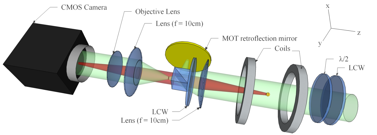
The probe beam is delivered to the science table by a polarization maintaining fiber where it is combined with the vertical MOT beam, sharing the same optical path through the science cell. This orientation allows for imaging perpendicular to an optical waveguide beam, allowing for non-destructive probing of experiments performed in the waveguide. Two liquid crystal wave-plates (LCW) enable dynamic switching of polarization of this optical line, allowing different polarizations of light for the MOT and imaging beams. A half-wave-plate is used to switch between dark ground and partial phase contrast imaging. This is enabled by changing the polarization of the probe beam which leads to a change in intensity of the background light that reaches the complementary metal-oxide semiconductor (CMOS) camera. A dual lens (f=10cm) setup ensures a detuning independent focus, with a subsequent objective lens magnifying the signal on the CMOS camera (Point Grey, model GS3-U3-41C6NIR-C) by times. Figure 3 shows a detailed schematic of the imaging setup.
3 Imaging Signal
The signal extracted by the CMOS camera can be calculated using a classical approach. Initially the probe beam is described by a vector field propagating along the -axis as in fig. 3. This field can be written as , where is the angle between the -polarized light and the axis of the polarizing beam-splitter (PBS). The probe beam is input on the cloud of atoms which are spin polarized in the z-direction by a large magnetic bias field of 165G (required to produce and hold the 85Rb condensate). Given this quantization axis, the probe light can be described by a superposition of and -polarized light. Assuming the probe light is far detuned, as is necessary for a non-destructive technique, it is reasonable to approximate the system as a two level atom with the corresponding complex refractive index given by
| (2) |
where is the cross-section for and -transitions respectively, is the detuning from an allowed transition at high field for and light respectively, and is the effective transition line-width. Each polarization component of the probe beam acquires a phase shift, , as a result of the interaction with the sample. The resultant light field can be re-expressed in the linear basis as , where . The intensity of each pixel of the CMOS camera will be proportional to , where is the unitary vector of the Cartesian coordinate. This leads to the nonlinear equation for the intensity of each pixel,
| (3) |
The corresponding density profile of the sample can be extracted from [14]
| (4) |
By setting and assuming we are far enough detuned that , it is possible to engineer the imaging system such that only the projection obtains a phase shift, leading to
| (5) |
where is the intensity of each pixel of a background picture. Under the assumption that the probe light is far detuned, equations (4) and (5) enable the density profile of the sample to be extracted.
4 Detuning of the probe beam
The magnetic field required to achieve and hold a 85Rb BEC imposes constraints on the imaging system. The magnetic field shifts the frequency differences between atomic states, effectively altering the frequency of the probe beam required to achieve a particular detuning from resonance. Since the destructiveness of the imaging system is dependent on this detuning, it is important to quantitatively understand the effect of the magnetic field on the atomic transitions.
At zero magnetic field the sublevels of each hyperfine state are degenerate. As the magnetic field is increased the degeneracy is lifted and the magnetic sublevels split. In the low field limit where the shift in energy of the atomic states is small compared the hyperfine splitting, the Zeeman effect is sufficient to calculate this change, and the states may be described the quantum numbers and . As the magnetic field increases beyond this regime, as is the case in most experimental applications, the splittings become more complex and it becomes necessary to numerically diagonalize the interaction Hamiltonian, where
| (6) |
and
| (7) |
where is the magnetic dipole constant, is the electric quadrupole constant, is the Bohr magneton, is the nuclear g-factor and is the Landé g-factor [23]. The Breit-Rabi equation provides a notable exception for the ground state manifold of the D transition in 85Rb and other species, where an analytic expression exist for the energy splittings [23].
Numerically diagonalizing and solving for the required magnetic field (G) we obtain the splittings shown in figure 4. The ground state levels are found to be in the usual Breit-Rabi regime where the quantum numbers and are appropriate. The excited states however are well into the anomalous Zeeman regime where the quantum numbers and are instead appropriate. Given the mix of regimes, the selection rules governing the transition from the ground to excited states are non-trivial.
In order to characterize the allowed transitions, spectroscopy was performed on the cloud at the required magnetic field with both polarizations of probe light ( and ). Since the condensate occupies the ground state magnetic sublevel , , the corresponding shift in energy was applied to the data so that the remaining shift is entirely due to the excited state splitting as shown in figure 5. Four peaks were observed; two for each polarization. Lorentzian fits were applied to the data with peaks determined at MHz (), MHz (), MHz () and MHz () with uncertainties given as the standard error from the fit. The peak at MHz was chosen for the imaging as it allowed the probe light to be blue-detuned arbitrarily far without interference from other resonances.
5 Characterization of destruction
It is necessary to fully characterize the destruction caused by the imaging system in order to operate optimally in terms of tolerable destruction with maximum signal. This characterization was achieve by taking in-trap images using the PPCI technique. The condensate was then dropped and imaged by the 22ms TOF absorption imaging system.

The results are shown in figure 6. The left plot shows the absorption signal as the in-trap imaging beam detuning changes. Close to resonance the condensate is completely destroyed. As the detuning increases this destruction decreases. The shaded band at the top of the image indicates one standard deviation from the mean variation run-to-run with no probe applied. The absorption signal is seen to approach this regime for large detunings with no change in atom number of cloud widths observed after expansion. Despite in-trap images being taken, the destruction is such that there is no discernible difference between the absorption image with and without the in-trap probe beam. Even at such large detuning and with such negligible destructive losses, the signal in-trap remains strong as seen on the right of figure 6. These 25 images are a subset of the 100 images taken over the course of 200ms. A Fourier discrete cosine transform filter has been applied to each image and each has been averaged over series of 10 runs for each detuning. In application to stochastic processes, such averaging is unavailable, and the signal drops accordingly. At GHz the signal has negligible decay and the corresponding dropped cloud closely resembles the cloud with no in-trap probe beam.

Integrating an area of the in-trap image where no signal is present allows a characterization of the noise. This area of integration is the same for both the signal and the noise. The resultant SNR is shown in figure 7. The peak signal is close to resonance, however it decays at an exponential rate. As the detuning is increase the signal decreases, but so too does the loss rate due to absorption. Far from resonance, at GHz, negligible decay occurs and the SNR lies within the rage of and corresponds to near optimal operation in terms of both destruction and signal. For applications where averaging cannot be used, such as stochastic processes, the SNR at this frequency drops to .
6 Measuring the response of a 85Rb condensate to a sudden change in scattering length
As a demonstration of the utility of this imaging system, a sequence of images of the response of the condensate to a rapid change in scattering length were taken. A 85Rb BEC of atoms is formed at . The scattering length is then ramped over ms to , after which it is rapidly jumped (50s) to a final value and observed using PPCI. The images are acquired with a period of 0.7ms. Figure 8 shows the evolution of the total atom number of the condensate in response to the jump. The ‘bosenova’ effect at negative scattering length is clearly evident [24]. A steady loss of atoms is observed at positive scattering length, while jumps to negative scattering length result in a delayed sudden ‘collapse’ of the cloud to a lower atom number [19]. As an additional feature of the imaging system, standard destructive absorption imaging provides a higher signal-to-noise image of the final cloud, post collapse. PPCI also gives access to width and CoM data which will allow detailed future analyses of the response of the condensate to such changes.
7 Conclusion
In this paper a minimally destructive imaging system combining the techniques of partial phase contrast and Faraday rotation imaging were presented. Such a system enables the sympathetic cooling process to be directly observed without compromising the BEC formation despite clouds containing very few atoms, typically of the order of . Analysis of signal to noise for a range of detunings indicate that at GHz detuning, at least images can be acquired with negligible destructive losses and a SNR of . The system provides a method for probing experimental regimes previously inaccessible using standard absorption imaging processes. Such regimes include stochastic processes such as dynamical instability of solitons, as well as experiments involving realtime feedback control of the BEC.
Acknowledgments
The authors gratefully acknowledge the support of the Australian Research Council Discovery program. The authors would like to heartily thank Russell Anderson from Monash University for his assistance in checking the anomalous Zeeman shifts, and Simon Cornish (Durham University) and Catherine Klauss (JILA) for their time cross-checking calibration data for the 85Rb Feshbach resonance.