Propulsion Without Propellent Mass;
a Time-Varying Electromagnetic Field Effect
Previous Section Next Section Contents
7. Far Fields Momentum Variation Rate
In this section we are interested to calculate the thrust by another approach than the one used in section 5. This approach is based on momentum conservation (subsection 7.2) of the whole system; charged particles and fields. It is an equivalent and complementary approach to the one in section 5. Like Poynting vector in section 6, far fields on spherical surface will be considered to calculate mechanical momentum variation rate or thrust. To do so, we need the Maxwell's stress tensor. Actually, the momentum flow (momentum per time unit per surface unit) transmitted across a surface is given by Maxwell's stress tensor.
The Maxwell's stress tensor at the observation point (![]() ,
t) in vacuum is given, in SI units, by [38]:
,
t) in vacuum is given, in SI units, by [38]:

We have used the dyadic form to express the tensor. This
is possible because it is a second rank tensor. ![]() is
the unit dyadic. We are interested to the following quantity:
is
the unit dyadic. We are interested to the following quantity:

The radial unit vector ![]() is
given in eq.(31). Some of tensor components appear in (45). They are expressed
with cylindrical components of fields. Tpq
gives the component, in direction "p", of field momentum which
goes out (in) across an elementary surface per time unit (momentum flow
per surface unit). This elementary surface has its normal vector in "q"
direction. By definition, space components p and q are perpendicular to
each other. If p = q, the momentum flow is perpendicular to the elemetary
surface (perpendicular or normal stress; "pressure"), otherwise
(p
is
given in eq.(31). Some of tensor components appear in (45). They are expressed
with cylindrical components of fields. Tpq
gives the component, in direction "p", of field momentum which
goes out (in) across an elementary surface per time unit (momentum flow
per surface unit). This elementary surface has its normal vector in "q"
direction. By definition, space components p and q are perpendicular to
each other. If p = q, the momentum flow is perpendicular to the elemetary
surface (perpendicular or normal stress; "pressure"), otherwise
(p![]() q), the momentum flow
is parallel to this surface (tangential stress or simply shear stress).
Two useful expressions of tensor components that appear in (45) are given
by:
q), the momentum flow
is parallel to this surface (tangential stress or simply shear stress).
Two useful expressions of tensor components that appear in (45) are given
by:
![]()

7.2. Momentum Conservation Law
Let's consider a volume V' wherein charge and current
densities are not zero. For example, in our problem V' = Vs1
+ Vs2; volumes of rings. Now,
we take a closed spherical volume V greater than V' and V includes V'.
Of course, we can take V as large as we want. It can be shown [39]
using Lorentz's force equation and Maxwell's equations [12-14]
in vacuum that:
with
![]()
the Newton's second law and with [39]:

S is the surface of V and dS is given by (34). ![]() is
the field momentum density at
is
the field momentum density at ![]() everywhere
inside V at the time t.
everywhere
inside V at the time t. ![]() is
the total mechanical momentum of all charged particles in the system inside
V.
is
the total mechanical momentum of all charged particles in the system inside
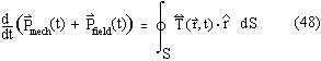
V. ![]() is the total field
momentum inside V. From equation (48), if the surface integral term is
zero we recover the familiar momentum conservation law for particles and
fields inside V. According to [39], the
integral term in (48) is the force per surface unit transmitted across
S and acting on the entire system composed by particles and fields inside
V.
is the total field
momentum inside V. From equation (48), if the surface integral term is
zero we recover the familiar momentum conservation law for particles and
fields inside V. According to [39], the
integral term in (48) is the force per surface unit transmitted across
S and acting on the entire system composed by particles and fields inside
V.
If we consider the static situation, the integral in (48)
is zero because only the induction fields are present and these fields
goes to zero more rapidly than the surface element when the sphere's radius
goes to infinity. We must remember that we can and we have to choose V
as large as we want to be sure to integrate over all points in space where
fields are not zero. In addition, d![]() /dt = 0 because the expression in (48) is time-independent in this particular
situation. So, as we know and as we have shown in section 5, the propulsive
force (in (49)) is zero in static case.
/dt = 0 because the expression in (48) is time-independent in this particular
situation. So, as we know and as we have shown in section 5, the propulsive
force (in (49)) is zero in static case.
To eliminate any oscillating contributions to the propulsive force, if they exist, and then keep only contributions able to give us a thrust, we take the temporal mean value of (48). The oscillating contributions can exist in a stationnary regime in which fields have periodic time dependance. Beside of the elimination of possible oscillating contributions to the force, there is a great advantage to take the temporal mean value of (48). Actually, temporal mean value of field momentum variation rate is zero in a stationnary regime when fields have time periodic properties. In other words:

because
![]()
According to eqs.(29) and (50), ![]() is
proportional to a product of a fields' couple. Because these fields change
periodically with a time period T, the equality in (52) holds. But, temporal
mean value of the field momentum in eq.(52) is not necessarily equal to
zero; fields can have a mean momentum in this situation.
is
proportional to a product of a fields' couple. Because these fields change
periodically with a time period T, the equality in (52) holds. But, temporal
mean value of the field momentum in eq.(52) is not necessarily equal to
zero; fields can have a mean momentum in this situation.
Result in (51) is quite important for us because if we consider a periodic stationnary regime and if we take the temporal mean value of eq.(48) we can see that, the temporal mean value of the force (mean value of the right term in (48)) is completely and exclusively transmitted to the mechanical part of the entire system in V. In particular, if this mean value of the force is zero, the mechanical part won't be never accelerated in a periodic stationnary regime.
7.3. Mechanical Momentum Variation
Rate (Force)
In this subsection we will use results in subsections
7.1 and 7.2 to solve our own problem. Electromagnetic fields in subsections
7.1 and 7.2 become, now, the sum of two electromagnetic fields; one is
created by Vs1 or ring j = 1
and the other is created by Vs2
or ring j = 2 (eqs.(14) and (15)). Furthermore, we have a periodic stationnary
regime and fields oscillation period is T (see section 6) so, according
to subsection 7.2, the temporal mean value of the (propulsive) force is
transmitted exclusively to the mechanical system (rings) in V and it is
given by:

with

It can be shown mathematically that only the z component (Fz) of the force in eq.(53) is different from zero. Physically this is not surprising because we have a rotation's symmetry around the z axis. From this and from eqs.(34), (45), (53) and (54) we have:

When we put appropriate fields given in eqs.(14) to (20), which are modified by eq.(35), into the right term of (55), we get summations over index j, j', a, a', b and b' and we can have j = j'. The electric field index, a and a', takes the values C, 2, R (see the upper index in eq.(14)). The magnetic index b and b' takes the values 1 and R (see the upper index in eq.(15)). The only electric fields couples (a, a') and the only magnetic fields couples (b, b') for which we can have a non-zero value for the Maxwell's stress tensor components in (55) with large distance ro over the sphere are: (2, 2) and (R, R) for electric fields and (R, R) for the magnetic one. The reason is similar to the one given in subsection 6.1 for the Poynting vector.
As for the Poynting vector, there are two couples (2, R) for which all electric fields decrease like 1/ro but they give no contribution to Fz because they cancel each other for large ro over the sphere. In other words,
sin(![]() )Re(
)Re(![]() )Re(
)Re(![]() )
- cos(
)
- cos(![]() )Re(
)Re(![]() )Re(
)Re(![]() )
= 0
)
= 0
which is the z component in eq.(45) (compare eqs.(A.19)
and (A.21) in appendix). The minus sign
in front the second term is the one that appears in eq.(44). In the above
expression we have removed, by simplicity, summation symbols, the "j"
subscripts, etc.. Furthermore, ![]() ~
(1/ro)² and
~
(1/ro)² and ![]() =
0 so, they don't contribute to Fz. According to all of this, eq.(55) becomes
(see details and definitions in appendix
eqs.(A.33) to (A.47)):
=
0 so, they don't contribute to Fz. According to all of this, eq.(55) becomes
(see details and definitions in appendix
eqs.(A.33) to (A.47)):

To get (56), we have used the reduced radius £o
of the sphere defined in eq.(36). In addition, co-ordinates over the sphere
given in equation (41) have been used to get (56). As in section 5, equation
(56) contains two kinds of contribution. The first one is purely non-radiative
(conservative); the (2, 2) contribution, n² ![]() 2(...),
because only the relativistic (electric) far field is in that term (see
appendix eqs.(A.46), (A.35), (A.37), (A.38)
and (A.41)). If n = 0, (no CDW), this contribution disappear. The second
is purely radiative ("dissipative"); (R, R) contributions,
2(...),
because only the relativistic (electric) far field is in that term (see
appendix eqs.(A.46), (A.35), (A.37), (A.38)
and (A.41)). If n = 0, (no CDW), this contribution disappear. The second
is purely radiative ("dissipative"); (R, R) contributions, ![]() ²
² ![]() R(...),
because it contains only radiative far fields (electric and magnetic) see
appendix eqs.(A.47), (A.36), (A.39), (A.40),
and (A.42) to (A.45). Clearly, n²
R(...),
because it contains only radiative far fields (electric and magnetic) see
appendix eqs.(A.47), (A.36), (A.39), (A.40),
and (A.42) to (A.45). Clearly, n² ![]() 2(...)
must be associated to the "electric contribution" of propulsive
force such as defined in section 5 and then
2(...)
must be associated to the "electric contribution" of propulsive
force such as defined in section 5 and then ![]() ²
²
![]() R(...), to the "magnetic
contribution" of this force. In section 5 (the near field approach),
the radiative electric field did not appear in the expression of Fz but
here, it is present and contributes to the "magnetic part" of
Fz.
R(...), to the "magnetic
contribution" of this force. In section 5 (the near field approach),
the radiative electric field did not appear in the expression of Fz but
here, it is present and contributes to the "magnetic part" of
Fz.
Fz is a force acting on material (charged) particles, so according to subsection 7.2 and the result given above (eq.(56)), relativistic far field ensures momentum conservation for the "electric contribution" to Fz (conservative part) and, radiative far fields (electric and magnetic) ensures momentum conservation for "the magnetic contribution" to Fz (dissipative part).
In this subsection, we will use eqs.(A.46)
and (A.47) to get some results for n² ![]() 2(...)
and also for
2(...)
and also for ![]() ²
² ![]() R(...),
which appear in eq.(56), as a function of
R(...),
which appear in eq.(56), as a function of ![]() (see fig.4). As in subsection 6.2, the reduced
radius £o of the sphere
goes to infinity (far fields). So, limits of impedances has been used (see
appendix eqs.(A.16) to (A.29)). Furthermore, eq.(56) has been evaluated
to give some numerical values of Fz (figs.5a and 5b).
(see fig.4). As in subsection 6.2, the reduced
radius £o of the sphere
goes to infinity (far fields). So, limits of impedances has been used (see
appendix eqs.(A.16) to (A.29)). Furthermore, eq.(56) has been evaluated
to give some numerical values of Fz (figs.5a and 5b).
From fig.4, we see that distributions have no asymmetry
relatively to ![]() =
= ![]() /2
(equator) when
/2
(equator) when ![]() = 0 or
= 0 or ![]() .
That means forces along z axis are equal and opposed. But, for all other
values of
.
That means forces along z axis are equal and opposed. But, for all other
values of ![]() and especially
for
and especially
for ![]() = ±
= ±![]() /2,
distributions are clearly asymmetric below and above equator. In these
cases, we have a resultant force along z.
/2,
distributions are clearly asymmetric below and above equator. In these
cases, we have a resultant force along z.
Furthermore, if for instance we consider asymmetric cases
on fig.4, we can verify that distributions of magnetic contribution to
Fz (![]() ) are mostly positive (e.g.
along +z) below equator (e.g. over
) are mostly positive (e.g.
along +z) below equator (e.g. over ![]() >
>
![]() /2) and mostly negative (e.g.
along -z) above equator (e.g. below
/2) and mostly negative (e.g.
along -z) above equator (e.g. below ![]() <
<
![]() /2). In other words, this contribution
to the force, closely associated with radiation such as mentioned above,
crosses the spherical surface from outside to inside. The most amazing
thing is that the distribution of electric contribution to Fz (
/2). In other words, this contribution
to the force, closely associated with radiation such as mentioned above,
crosses the spherical surface from outside to inside. The most amazing
thing is that the distribution of electric contribution to Fz (![]() )
does exactly the opposite; it crosses the surface from inside to outside.
These behaviors are also present for symmetric cases but without resultant
force.
)
does exactly the opposite; it crosses the surface from inside to outside.
These behaviors are also present for symmetric cases but without resultant
force.
It is clear from above that the magnetic part to the force Fz is similar to a "reaction mass" process excepted, expelled material particles are replaced here by radiative fields (photons). These photons are always expelled from rings toward infinity, from inside to outside the sphere, with momentum and in reaction to that (momentum conservation), a force in the opposite direction, from outside to inside the sphere, is given to the rings. This mechanism is quite similar to the radiation pressure [40-42] but here, unlike an interplanetary "sailplane", rings emit radiation instead of absorb it from external sources.
But clearly, electric contribution to Fz doesn't work like that. Probably, the best way to understand this contribution and also the magnetic one in this far field approach is to use the "fluid" point of view. We have found that the infinite plane at z = 0 and perpendicular to the z axis, plays an important role. Actually, this plane contains the rings' mass center and acts as an "airplane's wing" in a moving "fluid" when electric contribution to Fz is under consideration. For an asymmetric situation, things above and below this plane are different.
For the electric contribution, energy mean flow associated exclusively to the relativistic far field turns on closed paths as mentionned in subsection 6.2 and, near the plane-say, this flow is parallel to it, excepted close to z = 0, but it is different above and below this plane for an asymmetric case. Consequently, like over an airplane's wing in moving air, this creates a gradient of pression over the plane ("similar" to the Bernouilli's principle with material fluids). However, just below and above the plane, energy density (or "fluid density") is nearly the same. The existence of closed paths and the fact that the "fluid" ("photon gas") is not viscous (e.g. interaction between photons is zero in this situation) is another way to explain why there are no energy losses associated with (conservative) electric contribution to Fz (subsection 6.2).
Another equivalent way to understand this electric contribution, within the fluid point of view, is to think about vortices. In symmetric cases, there are vortices above and below the plane with same strength. They spin in opposite directions. In that case Fz = 0. But for asymmetric cases, the vortice on one side the plane is stronger than the one on the other side. In that case the plane and then the center of mass is "sucked" by the stronger vortice. If n = 0 (no CDW but only uniform currents) these vortices disappear.
Even if this flow moves on closed paths, its total angular momentum is still zero because these paths appear in pair and on each pair, flow turns in opposite direction. In addition, the opposite sign of Maxwell's stress tensor acts to maintain the flow on these closed paths. In some sense, this stress or pressure acts like a centripetal force on the "photon gas" and such a stress or pressure is closely correlated (by continuity in space) to the one, so to the force, applied directly over the plane-say.
Figure 5a presents results of Fz as a function of n for magnetic and electric contributions; equation (56). Results are quite similar to those that appear in section 5, fig.2. This is true for all parameters. Figure 5a gives results for few of them. But, quantitatively there is a difference among results in sections 5 and 7 as we can see on those figures. In subsection 7.5 we have explained those differences.
Finally, figure 5b gives
us dependence of Fz over the temporal phase-shift ![]() for
both contributions (magnetic and electric). A sinus function has been obtained
exactly as in section 5, eq.(27). Figure
5b presents those results for specific values of n,
for
both contributions (magnetic and electric). A sinus function has been obtained
exactly as in section 5, eq.(27). Figure
5b presents those results for specific values of n, ![]() /R'
and
/R'
and ![]() /D. This sinus function
is also obtained for any other values of these last parameters.
/D. This sinus function
is also obtained for any other values of these last parameters.
7.5. Difference with Section 5
In subsection 7.4, we've observed a quantitative (not qualitative) difference among results for Fz given in figures 5a and 2. This difference comes from the fact that we have neglected, in section 5 (eq.(26)), contibutions coming from j = j' because they are infinite but here, in section 7, these contributions have been taken into account. To remove them (in subsection 7.3), we would have to use another volume V'' = V - (Vs1 + Vs2) instead of V, and then another closed surface S'' = S - (Ss1 + Ss2) instead of S into eq.(48). But it's a complicated task because Vs1, Vs2, Ss1 and Ss2 go to zero; they are volumes and surfaces of filiform rings.
If such contributions (j = j') to Fz are infinite because
rings are filiform (section 5), how is it possible, here in section 7,
to get finite results for Fz if preceding contributions have not been removed
? The answer is quite simple, to get our results (section 7) we have used
far fields identical to the ones created by filiform rings but, implicitly,
we've supposed fields everywhere inside of volume V were finite and then,
in particular, inside Vs1 and
Vs2 ("inside rings"
!). So, in other words, implicitly it is like if we have used non-filiform
rings, torus with a cross section Ro
for instance like the ones described in section 4. Physically speaking
we can expect that, when we go to infinity, fields created by such non-filiform
rings, with cross section Ro
> 0 but much smaller than R', D and ![]() ,
must be identical to the ones created by filiform rings with Ro
= 0 and with same R', D and
,
must be identical to the ones created by filiform rings with Ro
= 0 and with same R', D and ![]() .
.
However inside rings, current and charge distributions
cannot be exactly the same for filiform rings and non-filiform ones. Actually,
according to section 4, if inside a non-filiform ring the ![]() dependence
of these distributions is the same as in filiform one, it is certainly
not the case for their
dependence
of these distributions is the same as in filiform one, it is certainly
not the case for their ![]() dependence along the cross section. In fact, for n = 0 results for Fz (figs.
2 and 5a) are equal because there is no CDW, only a uniform current. But
for n
dependence along the cross section. In fact, for n = 0 results for Fz (figs.
2 and 5a) are equal because there is no CDW, only a uniform current. But
for n![]() 0, we know from
section 4, the phase of charge and current distributions change with the
radius r (r < Ro) along the
cross section and then some cancellation effects, in their fields, must
occur between a distribution at r and another one at another r. So outside
rings, "near" fields are smaller than the ones created by filiform
rings and then Fz is smaller. But for large distances, far fields seem
to be created by an effective distribution equal to the one used in section
5.
0, we know from
section 4, the phase of charge and current distributions change with the
radius r (r < Ro) along the
cross section and then some cancellation effects, in their fields, must
occur between a distribution at r and another one at another r. So outside
rings, "near" fields are smaller than the ones created by filiform
rings and then Fz is smaller. But for large distances, far fields seem
to be created by an effective distribution equal to the one used in section
5.
We expect that this quantitative difference between both approaches (sections 5 and 7) is simply an artefact and it will disappear if a more realistic system (non-filiform rings) is used because both approaches are rigorously equivalent.
Previous Section Next Section Contents